Wire view of aem ems – AEM 30-6051 Series 2 Plug & Play EMS User Manual
Page 9
Page 9 of 15
Application Notes for EMS P/N 30-6051
J30A/A1, J32A1/A2, J35A4
Make: Acura/Honda
Spare
Injector
Drivers:
Injector 12, Pin A10
Model:
Integra, 2.3CL, Accord, Civic
Spare Injector Drivers:
Injector 9, Pin A12
Years Covered:
1999-2004
Spare Injector Drivers:
Injector 11, Pin A14
Engine Displacement:
3.0L, 3.2L, 3.5L
Spare Injector Drivers:
Injector 8, Pin B16
Engine Configuration:
V6
Spare Injector Drivers:
Injector 10, Pin C11
Firing Order:
1-4-2-5-3-6
Spare Injector Drivers:
Injector 7, Pin D2
N/A, S/C or T/C:
N/A
Spare Coil Drivers:
Coil 7, Pin A13
Load Sensor Type:
MAP
Spare Coil Drivers:
Coil 8, Pin A22
MAP Min:
0.32V @ -13.9 psi
Boost Solenoid:
PW 2, Pin D16
MAP Max:
4.84V @ 10.94 psi
Spare PWM Freq Driver: PW 3, Pin A11
# Coils:
6
EGT 1 Location:
Pin A5
Ignition driver type:
0-5V Falling Edge trigger
EGT 2 Location:
Pin D7
# of Injectors:
6 (Inj 1-6)
EGT 3 Location:
Pin A30
Factory Injectors:
240cc/min
EGT 4 Location:
Pin C5
Factory Inj Resistors:
No
Spare 0-5V Channels:
ADCR 11, Pin C6
Injection Mode:
Sequential
Spare 0-5V Channels:
ADCR 13, Pin C24
Knock Sensors used:
1 (Knock 1)
Spare 0-5V Channels:
ADCR 14, Pin D8
Lambda Sensors used:
Spare Low Side Driver:
Low side 1, Pin A2
2 (wideband sensors required,
original O2 sensor not supported)
Spare Low Side Driver:
Low side 3, Pin A3
Idle Motor Type:
Duty-controlled solenoid
Spare Low Side Driver:
Low side 5, Pin A4
Main Relay Control:
No
Spare Low Side Driver:
Low side 4, Pin A6
Crank Pickup Type:
Magnetic (2-wire)
Spare Low Side Driver:
Low side 12, Pin A8
Crank Teeth/Cycle:
24
Spare Low Side Driver:
Low side 6, Pin A17
Cam Pickup Type:
Magnetic (2-wire)
Spare Low Side Driver:
Low side 7, Pin A19
Cam Teeth/Cycle:
3
Spare Low Side Driver:
Low side 2, Pin C1
Transmissions Offered:
Manual/Automatic
Check Engine Light:
Low side 10, Pin A18
Trans Supported:
Manual
Spare High Side Driver:
High side 2, Pin B7
Drive Options:
FWD
Spare High Side Driver:
High side 4, Pin D4
Supplied Connectors:
N/A
Spare High Side Driver:
High side 3, Pin D13
AEM Extension/patch harness
30-2982
Spare Switch Input:
Switch 5, Pin A26
AEM Plug/pin kit
35-2610
Spare Switch Input:
Switch 1, Pin A32
Spare Switch Input:
Switch 3, Pin D12
A/C Switch Input:
Switch 6, Pin A27
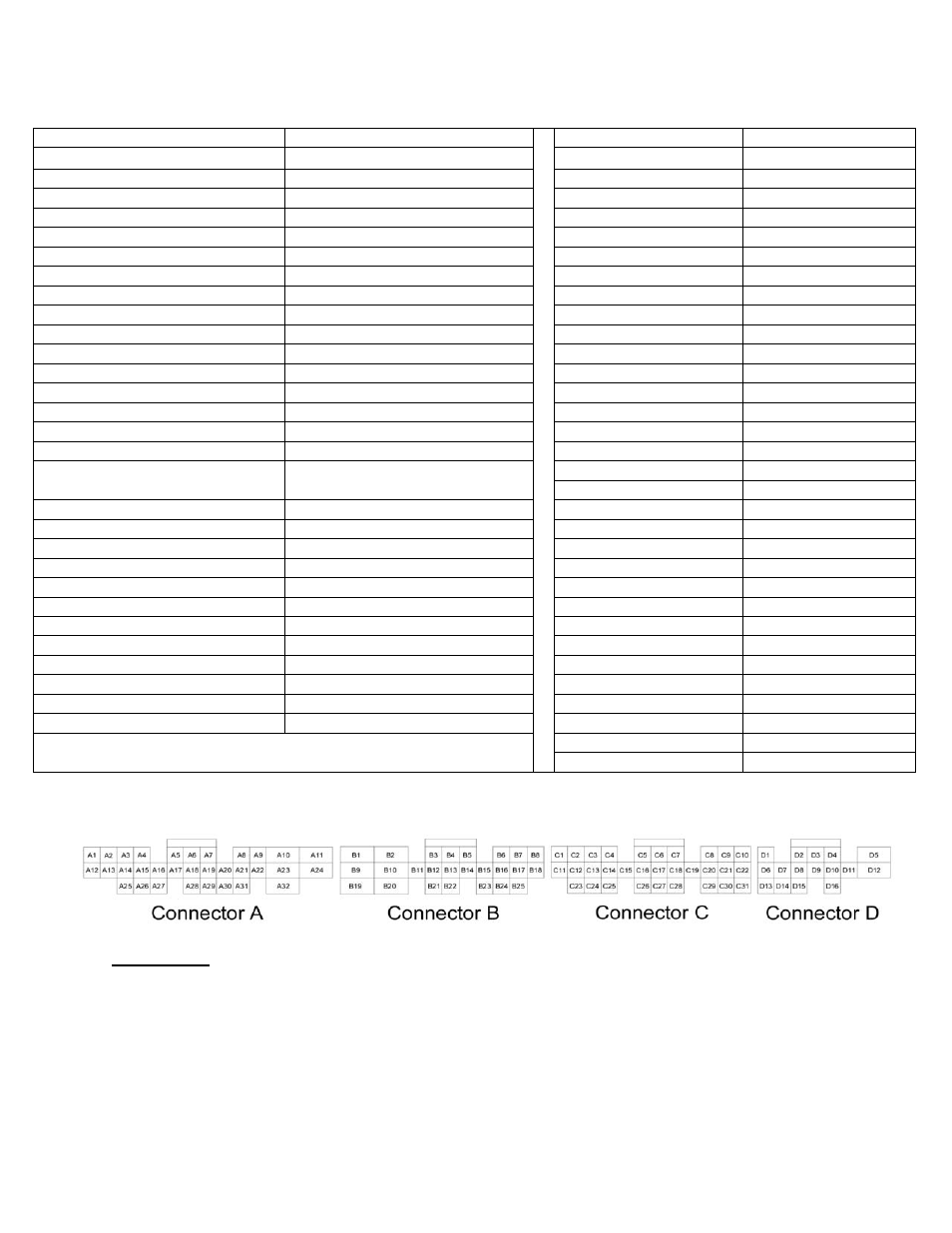
Wire View of AEM EMS
WARNING:
*All switch input pins must connect to ground; the switch should not provide 12V power
to the EMS because that will not be detected as on or off.