Wire view of aem ems – AEM 30-6051 Series 2 Plug & Play EMS User Manual
Page 14
Page 14 of 15
Connection Diagram for EMS P/N 30-6051
Pin
1999-2002 Honda Accord V6 J30A1;
2002-2004 Honda Odyssey 3.5L V6 J35A4
1999-2003 Acura 3.2 TL/CL V6 J32A1;
2002-2003 Acura 3.2 TL/CL V6 Type S J32A2;
AEM EMS 30-6051
I/O
Notes
D1
Lock-up control solenoid valve
← Injector
5
Output
Available, switched ground, 1.5A max (connected to B15)
D2
Shift control solenoid valve B
← Injector
7
Output
Available, switched ground, 1.5A max
D3
Shift control solenoid valve C
← Idle
1
Output
Available, switched ground, 1.5A max
D4
---
A/T gear position switch signal
High side 4
Output
Available, switched input
D5
Battery flyback solenoid
← Idle
4
Output
Available, switched +12V, 1.5A max
D6
A/T reverse switch
← Sensor
+5V
Output
Available, sensor +5V output
D7
Shift control solenoid valve A
← EGT
2
Input
Available, jumper set for 0-5V input
D8
A/T D3 sw
A/T D4 sw
ADCR14
Input
Available, 0-5V input, 100Kohm pull up resistor to +5V
D9
A/T D4 sw (1999-2002 Honda Accord V6 J30A1);
A/T D5 sw (2002-2004 Honda Odyssey V6 J35A4)
A/T D5 sw
Sensor ground
Output
Available, sensor ground output
D10
Countershaft speed sensor +
← CAN1H
---
Dedicated, CAN high side
D11
Mainshaft speed sensor +
←
Vehicle Speed (T3)
Input
PnP for vehicle speed sensor input
D12
Mainshaft speed sensor -
← Switch
3
Input
Available, switched +12V input, 1.5A max
D13
Park switch (1999 Honda Accord V6 J30A1);
2nd clutch pressure switch (2000 Honda Accord V6
J30A1);
3rd oil pressure switch
High side 3
Output
Available, switched +12V output, 1.5A max
D14
A/T 2 sw
A/T 3 sw
CAN1L
---
Dedicated, CAN low side
D15
A/T 1 sw
A/T 2 sw
Baro Volts
Input
Available, 0-5V input
D16
Countershaft speed sensor -
← PW
2
Output
Available, boost solenoid output
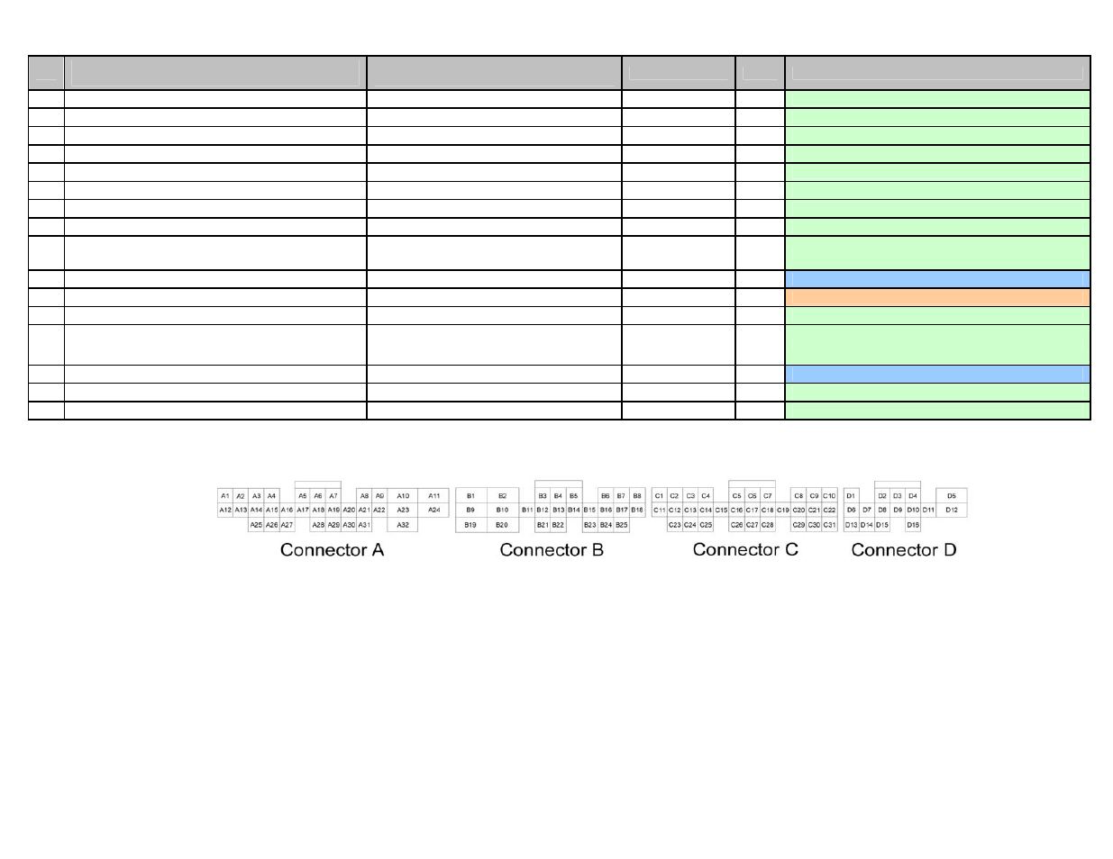
Wire View of AEM EMS