AEM 30-3703 Infinity-8/10/12 Mini-Harness User Manual
Page 19
19
© 2014 AEM Performance Electronics
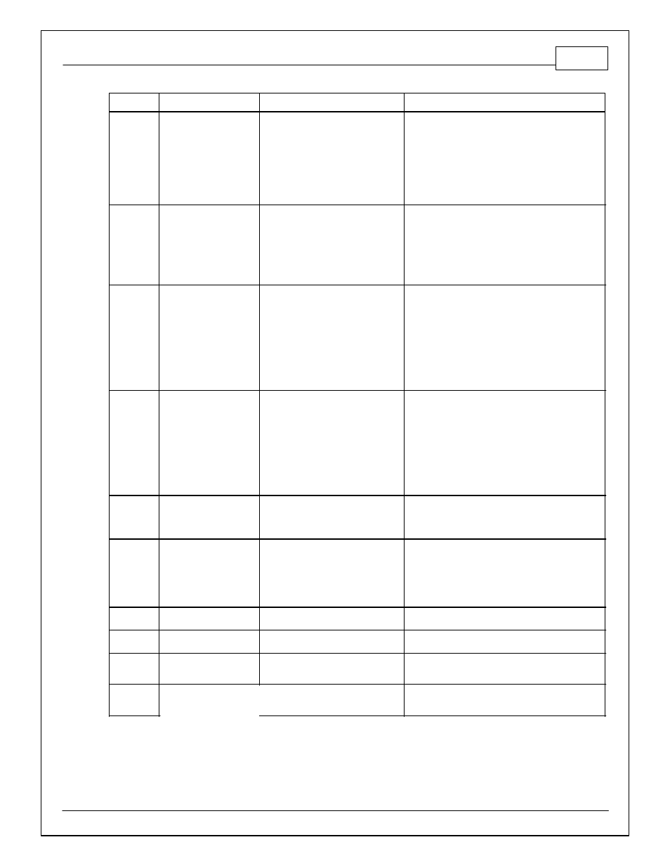
Infinity Pin
Hrdwr Ref.
Hardware Specification
Notes
C2-33
Analog_In_20
12 bit A/D, 100K pullup to 5V
0-5V analog signal. Use +5V Out pins as power
supply and Sensor Ground pins as the low
reference. Do not connect signals referenced to
+12V as this can permanently damage the ECU.
C2-34
Analog_In_21
12 bit A/D, 100K pullup to 5V
0-5V analog signal. Use +5V Out pins as power
supply and Sensor Ground pins as the low
reference. Do not connect signals referenced to
+12V as this can permanently damage the ECU.
Normally used as 3 Step Enable Switch input.
C2-35
Analog_In_22
12 bit A/D, 100K pullup to 5V
0-5V analog signal. Use +5V Out pins as power
supply and Sensor Ground pins as the low
reference. Do not connect signals referenced to
+12V as this can permanently damage the ECU.
Normally used as USB Logging Request input.
C2-36
Analog_In_23
12 bit A/D, 100K pullup to 5V
0-5V analog signal. Use +5V Out pins as power
supply and Sensor Ground pins as the low
reference. Do not connect signals referenced to
+12V as this can permanently damage the ECU.
Normally used as Charge Out Pressure input.
C2-37
Digital_In_6
No pullup. Will work with TTL
signals.
Input can be assigned to different pins. See Setup
Wizard page Input Function Assignments for input
mapping options.
C2-38
Digital_In_7
No pullup. Will work with TTL
signals.
See ClutchSwitch 1-axis table for setup options.
Input can be assigned to different pins. See Setup
Wizard page Input Function Assignments for input
mapping options.
C2-39
Power Ground_In
Power Ground
Connect directly to battery ground
C2-40
Power Ground_In
Power Ground
Connect directly to battery ground
C2-41
CanH_B_Out
Dedicated High Speed CAN
Transceiver
Not used
C2-42
CanL_B_Out
Dedicated High Speed CAN
Transceiver
Not used