AEM 30-3703 Infinity-8/10/12 Mini-Harness User Manual
Page 17
17
© 2014 AEM Performance Electronics
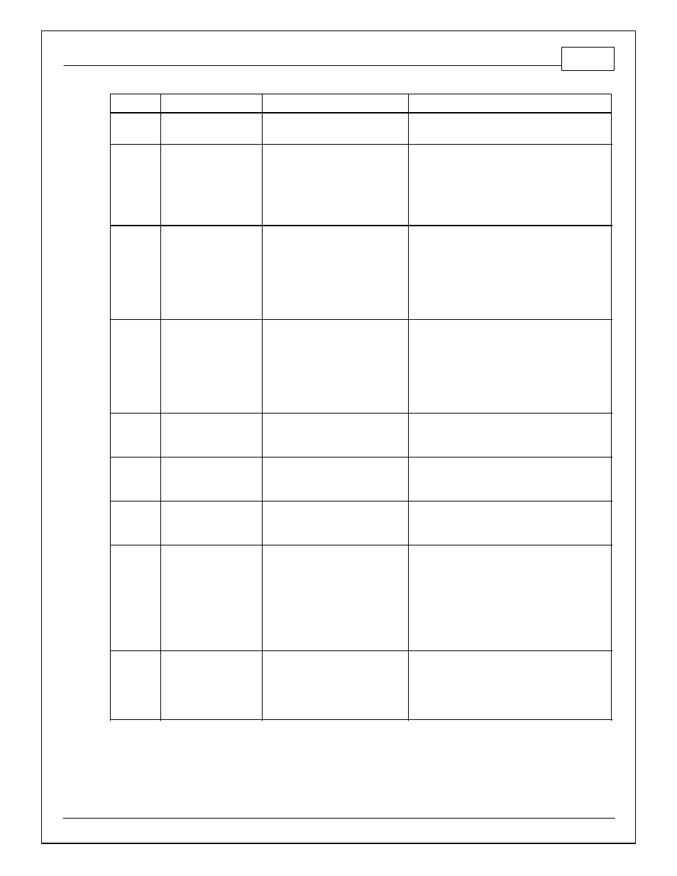
Infinity Pin
Hrdwr Ref.
Hardware Specification
Notes
C2-11
Injector 12_Out
Saturated or peak and hold, 3A max
continuous
Not used
C2-12
Analog_In_17
12 bit A/D, 100K pullup to 5V
0-5V analog signal. Use +5V Out pins as power
supply and Sensor Ground pins as the low
reference. Do not connect signals referenced to
+12V as this can permanently damage the ECU.
Normally used as A/C Analog Request input.
C2-13
Analog_In_18
12 bit A/D, 100K pullup to 5V
0-5V analog signal. Use +5V Out pins as power
supply and Sensor Ground pins as the low
reference. Do not connect signals referenced to
+12V as this can permanently damage the ECU.
Normally used as DBW APP1.
C2-14
Analog_In_19
12 bit A/D, 100K pullup to 5V
0-5V analog signal. Use +5V Out pins as power
supply and Sensor Ground pins as the low
reference. Do not connect signals referenced to
+12V as this can permanently damage the ECU.
Normally used as DBW APP2.
C2-15
Analog_In_Temp_4
12 bit A/D, 2.49K pullup to 5V
Normally used as Charge Out Temperature input.
C2-16
Analog_In_Temp_5
12 bit A/D, 2.49K pullup to 5V
Normally used as Airbox Temperature input.
C2-17
Analog_In_Temp_6
12 bit A/D, 2.49K pullup to 5V
Normally used as Fuel Temperature input.
C2-18
Analog_In_13
12 bit A/D, 100K pullup to 5V
0-5V analog signal. Use +5V Out pins as power
supply and Sensor Ground pins as the low
reference. Do not connect signals referenced to
+12V as this can permanently damage the ECU.
See Setup Wizard Oil Pressure page for setup
options. See OilPressure [psig] for channel data.
C2-19
Analog_In_14
12 bit A/D, 100K pullup to 5V
0-5V analog signal. Use +5V Out pins as power
supply and Sensor Ground pins as the low
reference. Do not connect signals referenced to
+12V as this can permanently damage the ECU.