AEM 30-3703 Infinity-8/10/12 Mini-Harness User Manual
Page 15
15
© 2014 AEM Performance Electronics
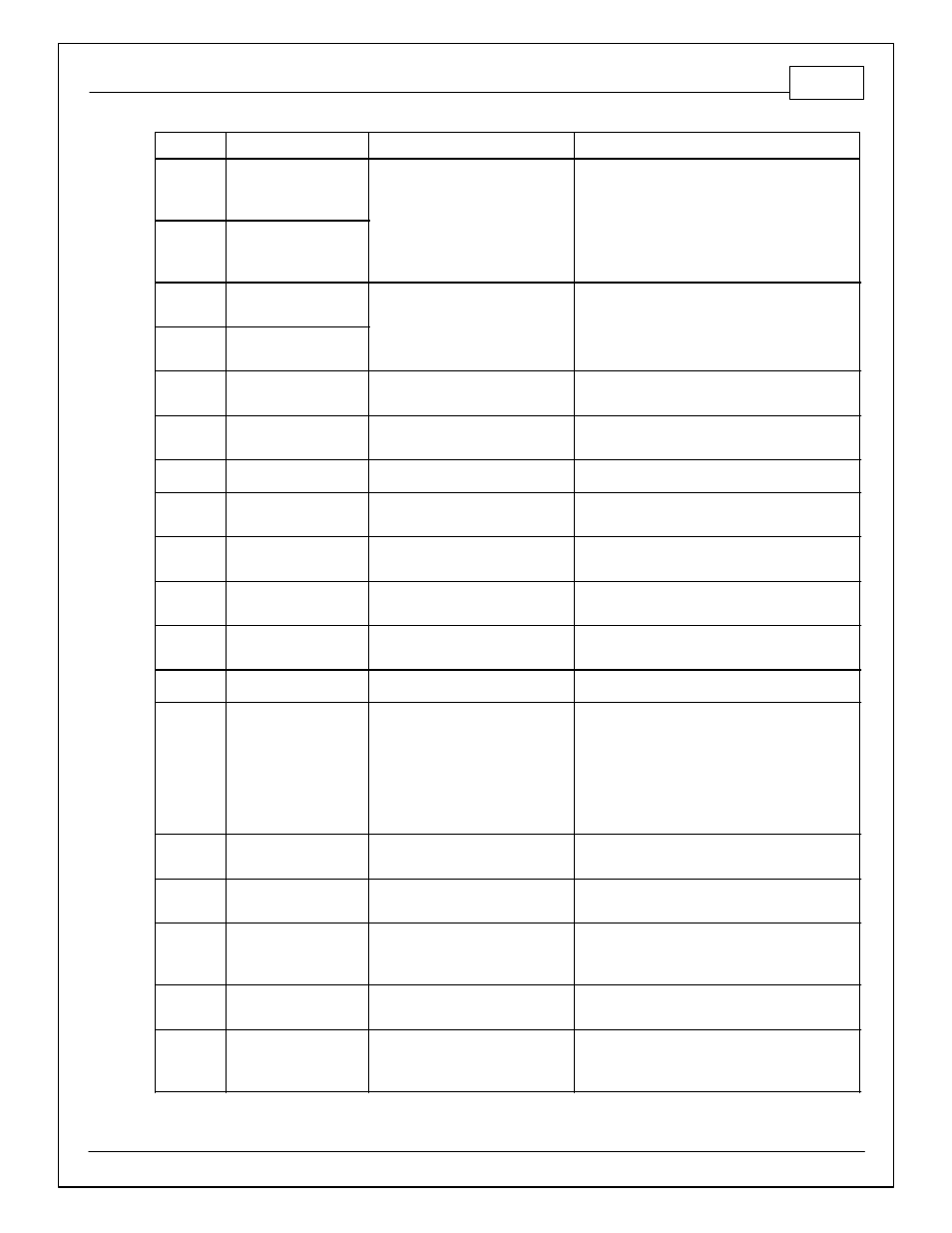
Infinity Pin
Hrdwr Ref.
Hardware Specification
Notes
C1-49
VR+_In_2
Differential Variable Reluctance
Zero Cross Detection
See Non Driven Wheel Speed Calibration in the
Setup Wizard Vehicle Speed page.
C1-50
VR-_In_2
C1-51
VR-_In_3
Differential Variable Reluctance
Zero Cross Detection
See Driven Wheel Speed Calibration in the Setup
Wizard Vehicle Speed page.
C1-52
VR+_In_3
C1-53
DBW1 Motor -_Out
5.0A max Throttle Control Hbridge
Drive
+12V to close.
C1-54
DBW1 Motor +_Out
5.0A max Throttle Control Hbridge
Drive
+12V to open.
C1-55
Power Ground_In
Power Ground
Connect directly to battery ground
C1-56
Injector 6_Out
Saturated or peak and hold, 3A max
continuous
Injector 6
C1-57
Injector 5_Out
Saturated or peak and hold, 3A max
continuous
Injector 5
C1-58
Injector 4_Out
Saturated or peak and hold, 3A max
continuous
Injector 4
C1-59
Injector 3_Out
Saturated or peak and hold, 3A max
continuous
Injector 3
C1-60
Power Ground_In
Power Ground
Connect directly to battery ground
C1-61
+12V_In
12 volt power from relay
12 volt power from relay. Relay must be
controlled by +12V Relay Control signal, pin C1-29
above.
C1-62
Injector 2_Out
Saturated or peak and hold, 3A max
continuous
Injector 2
C1-63
Injector 1_Out
Saturated or peak and hold, 3A max
continuous
Injector 1
C1-64
+12V_In
12 volt power from relay
12 volt power from relay. Relay must be
controlled by +12V Relay Control signal pin C1-29
above.
C1-65
+12V_SW_In
10K pulldown
Full time battery power must be available at C1-
10 before this input is triggered.
C1-66
Analog_In_Temp_1
12 bit A/D, 2.49K pullup to 5V
See "Coolant Temperature" Setup Wizard for
selection.