AEM 30-3509 Infinity Plug & Play Harnesses - Honda/Acura OBD2B User Manual
Page 8
8
© 2014 AEM Performance Electronics
P/N 30-3509
Infinity
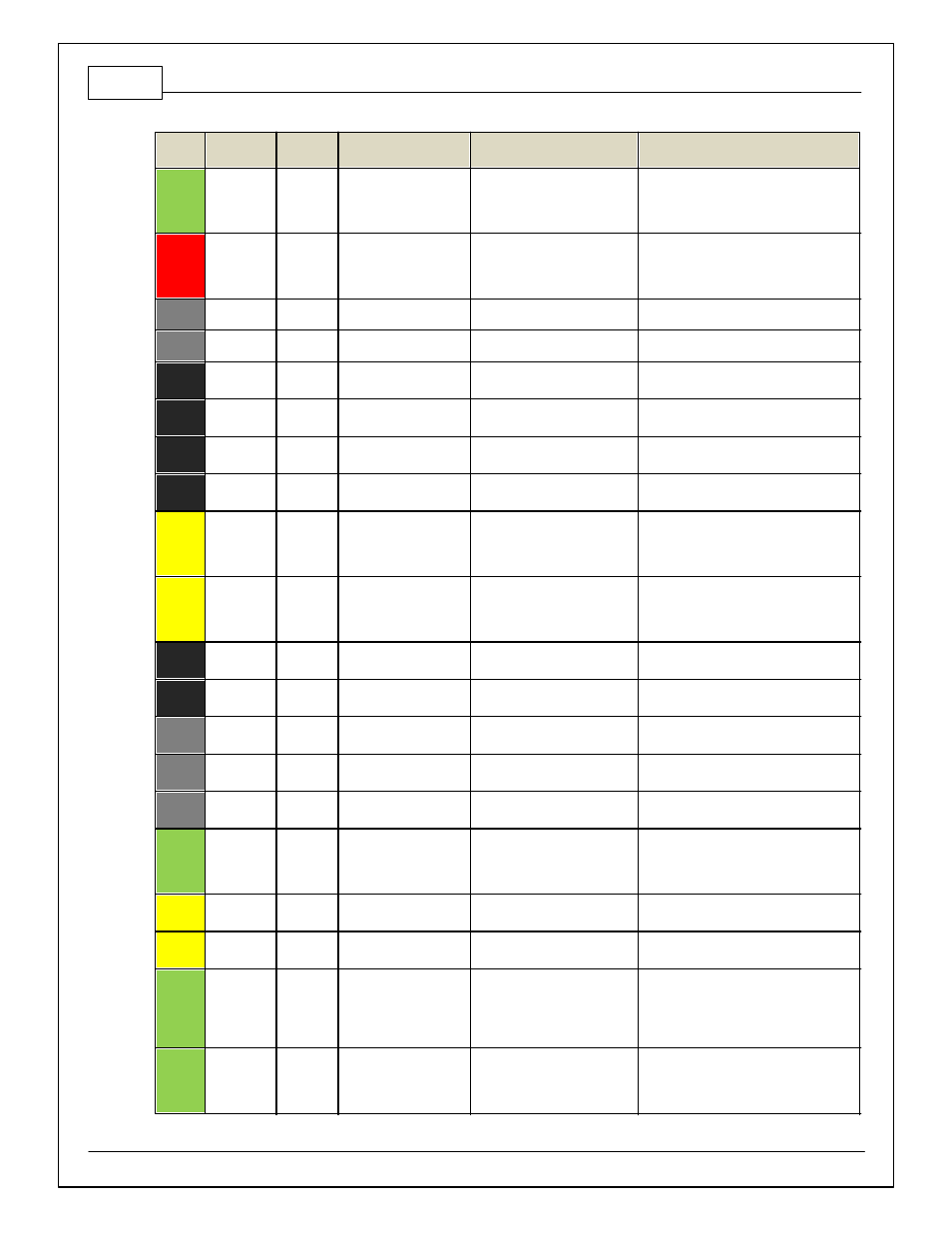
Pin
Infinity
Assignment
Honda
Pin
Honda Description
Infinity Hardware
Specification
Notes
13
Coil 2
Ignition Coil Pulse No. 2
25 mA max source current
0–5V f alling edge f ire. Do NOT connect
directly to coil primary . Must use an ignitor
or CDI that accepts a f alling edge f ire
signal.
14
Coil 1
B13
Ignition Coil Pulse No. 1
25 mA max source current
0–5V f alling edge f ire. Do NOT connect
directly to coil primary . Must use an ignitor
or CDI that accepts a f alling edge f ire
signal.
15
---
---
---
---
---
16
---
---
---
---
---
17
VR0 (+) -
Crank
C9
CKP -
Dif f erential Variable Reluctance
Zero Cross Detection
See Setup Wizard page Cam/Crank f or
options.
18
VR0 (-) -
Crank
C8
CKP +
Dif f erential Variable Reluctance
Zero Cross Detection
See Setup Wizard page Cam/Crank f or
options.
19
VR1 (-) -
Cam
C29
TDC1 +
Dif f erential Variable Reluctance
Zero Cross Detection
See Setup Wizard page Cam/Crank f or
options.
20
VR1 (+) -
Cam
C30
TDC1 -
Dif f erential Variable Reluctance
Zero Cross Detection
See Setup Wizard page Cam/Crank f or
options.
21
LS 2
A20
Radiator Fan Control
Lowside switch, 4A max, No
internal f ly back diode.
See Setup Wizard Page "LowSide
Assignment Tables" f or output assignment
and 2D table "LS2_Duty [%]" f or on/of f
activ ation.
22
LS 3
B23
Idle Air Control Valv e
Lowside switch, 4A max with
internal f ly back diode. Inductiv e
load should NOT hav e f ull time
power.
See Setup Wizard page and corresponding
Tables f or Idle Air Control.
23
Sensor
GND
C7
Sensor Ground 1
Dedicated analog ground
Analog 0–5V sensor ground
24
Sensor
GND
C18
Sensor Ground 2
Dedicated analog ground
Analog 0–5V sensor ground also f ound on
aux connector
25
Digital 0 -
Crank
---
---
10K pullup to 12V. Will work with
ground or f loating switches.
Not used f or this application
26
Digital 1 -
Cam1
---
---
10K pullup to 12V. Will work with
ground or f loating switches.
Not used f or this application
27
Digital 2 -
Cam2
---
---
10K pullup to 12V. Will work with
ground or f loating switches.
Not used f or this application
28
Digital 3 –
Flex Fuel
---
---
10K pullup to 12V. Will work with
ground or f loating switches.
Found on the Aux Connector. Input can be
assigned to dif f erent pins. See Setup
Wizard page Input Function Assignments
f or input mapping options.
29
Digital 4 -
VSS#1
C23
Vehicle Speed Sensor
10K pullup to 12V. Will work with
ground or f loating switches.
See Setup Wizard page Vehicle Speed f or
calibration constant.
30
Digital 5 -
A27
A/C Switch Signal
10K pullup to 12V. Will work with
ground or f loating switches.
See Setup Wizard Input Function
Assignments page f or A/C activ ation.
31
Digital 6 –
Turbo Speed
---
---
10K pullup to 12V. Will work with
ground or f loating switches.
Found on the Aux Connector. Input can be
assigned to dif f erent pins. See Setup
Wizard page Input Function Assignments
f or input mapping options.
*Coil 7 f or Inf inity 8h.
32
Digital 7 -
---
---
10K pullup to 12V. Will work with
ground or f loating switches.
Input can be assigned to dif f erent pins.
See Setup Wizard page Input Function
Assignments f or input mapping options.
*Coil 8 f or Inf inity 8h