Installing the pipe and pump – PHCC Pro Series Pro Series C11 User Manual
Page 4
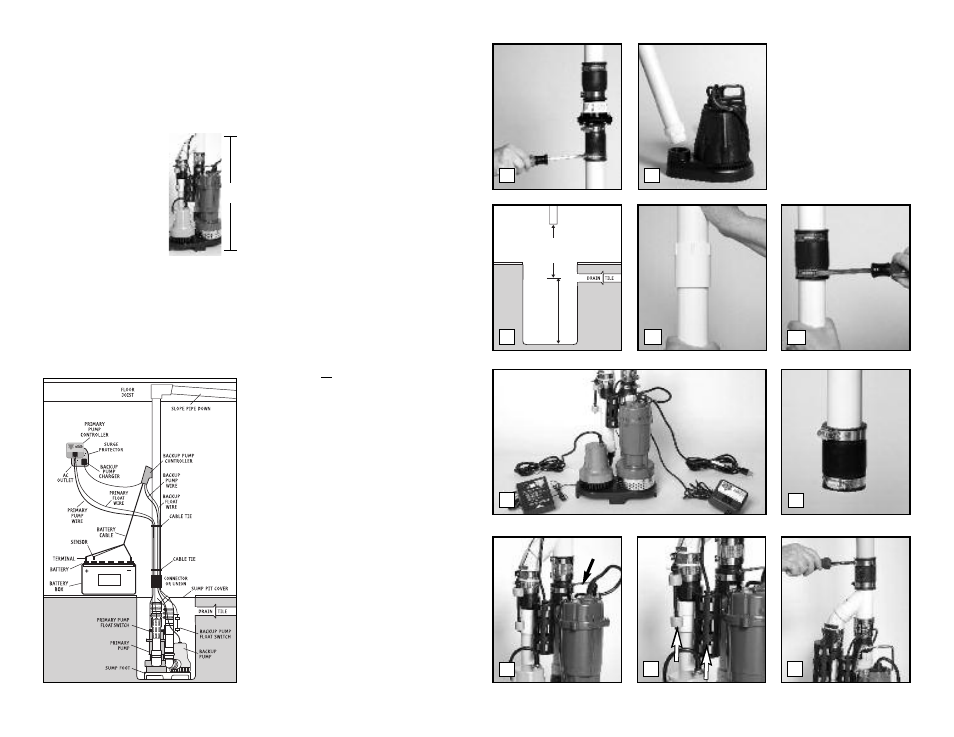
Installing the Pipe and Pump
The Pro Series Pair of Pumps combination system
is compact and will fit in a sump pit as small as
12” wide. It measures 23¾” inches from the
bottom of the pump stand to the top of the Y-
connector where it will be attached to the
discharge pipe.
Use a pit that conforms to all
local codes, and check the
code to see if a gate valve or
ball valve if is required.
The discharge pipe must be
positioned in a downward
slope when it exits the
building, so any remaining
water will drain away. Failure to do this will
prevent water from exiting the pit, and damage
the pump if the line freezes.
The system should be placed on a flat surface free
from dirt and debris. If the bottom of the sump
pit is not clean, remove as much of the debris as
possible. The pumps are attached to a sump foot
(stand) to raise them above any debris.
If you are replacing an old sump pump, unplug
the pump from the outlet.
1. Remove the check valve or rubber union.
Discard the check valve.
The Pro Series
system contains built-in check valves, so the
old check valve will not be needed. If the
existing system is installed without a check
valve or rubber union, saw the pipe apart
above the sump pit. (Refer to the diagram in
step 3)
2. Remove the old pump from the pit, and
unscrew the pipe and pipe adapter from the
pump. You can use this pipe for the rest of
the installation.
3. Measure the distance from the bottom of the
sump pit to the end of the discharge pipe.
Subtract 24¾” inches (the height of the pump
system + 1 inch). Cut a piece of 1-1/2” rigid
PVC pipe to that length.
4. (a) Connect this piece to the discharge pipe
by cementing the two pieces together with a
1-1/2” PVC pipe connector.
(Follow the
instructions on the PVC pipe cleaner and
cement.) OR, (b) connect the two pieces of
pipe together with a rubber union.
5. Remove the attached cords and controllers
from the carton and place them next to the
pump system.
BE SURE THE CORDS AND
CONTROLLERS DO NOT FALL INTO THE SUMP PIT.
6. Loosen the hose clamps on the enclosed
rubber union, and slide the union up on the
discharge pipe until it is even with the
bottom of the pipe.
7. Lift the combination system by the handle on
the primary pump and lower it into the sump
pit. Make sure it is level.
8. Inspect the two float switches. They should
both be vertical.
9. Position the top of the pump system pipe so
that it is directly below the discharge pipe.
Slide the rubber union down until ½ of the
rubber union is covering the pump pipe, and
the other half is covering the bottom of the
discharge pipe.
Tighten the hose clamp
screws securely.
Page 3
23
3
/
4
”
CUT
PVC TO
THIS
LENGTH
1
2
4b
4a
3
5
7
8
9
23
3
/
4
“
Diagram A
6
LIFT