Hornady Lock-N-Load Powder Measure with Case-Activated Powder Drop User Manual
Page 12
- 11 -
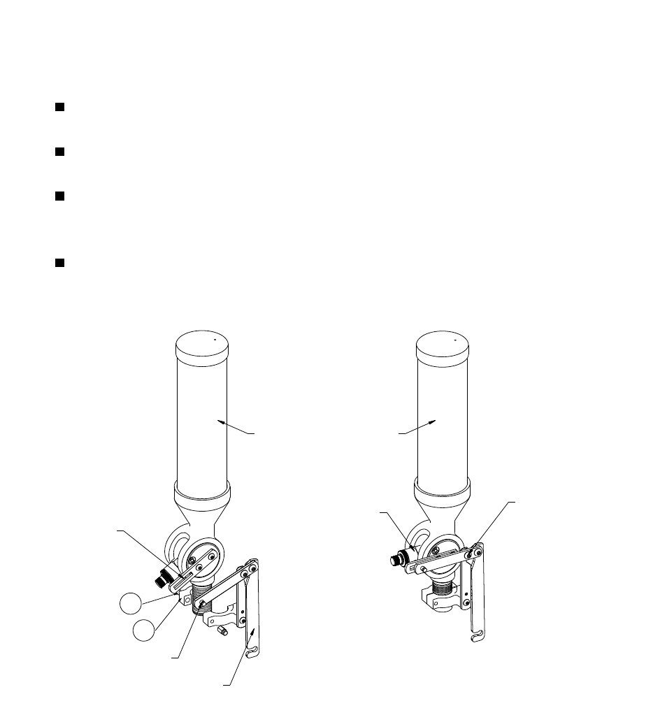
Step 2: Upper Bracket Assembly
Slide the Upper Bracket Assembly onto the Powder Measure.
Engage Drive Link Pin (#10) into the Rotor Arm Slot.
Adjust the position of the Upper Assembly so that the drive link pivot is across from
the centerline.
Tighten the two Button Head Cap Screws (#1) and (#9). The longest screw 10-32 X
1.25 goes in the front hole. Screw on the Spring Nut (#13) to the end of the 10-32 X
1.25 screw.
Fig. 2: Upper Bracket
Assembly.
2
9
PIVOT LOCATED
ACROSS FROM
ROTOR CENTERLINE
ROTOR “CENTERED”
UPPER ASSEMBLY
DRIVE LINK PIN
L-N-L POWDER MEASURE
ROTOR
ARM SLOT