Servicing instructions – L.B. White Pilot User Manual
Page 63
For U
Units W
With FFlapper:
1. Shut off gas supply and disconnect heater from
electrical source.
2. Disconnect air-proving switch leads.
3. Some models may have the air-proving switch
mounting nuts located on the inside of the fan
housing. Remove the motor and fan assembly from
the housing. Remove the nuts and pull the switch and
screws from the housing.
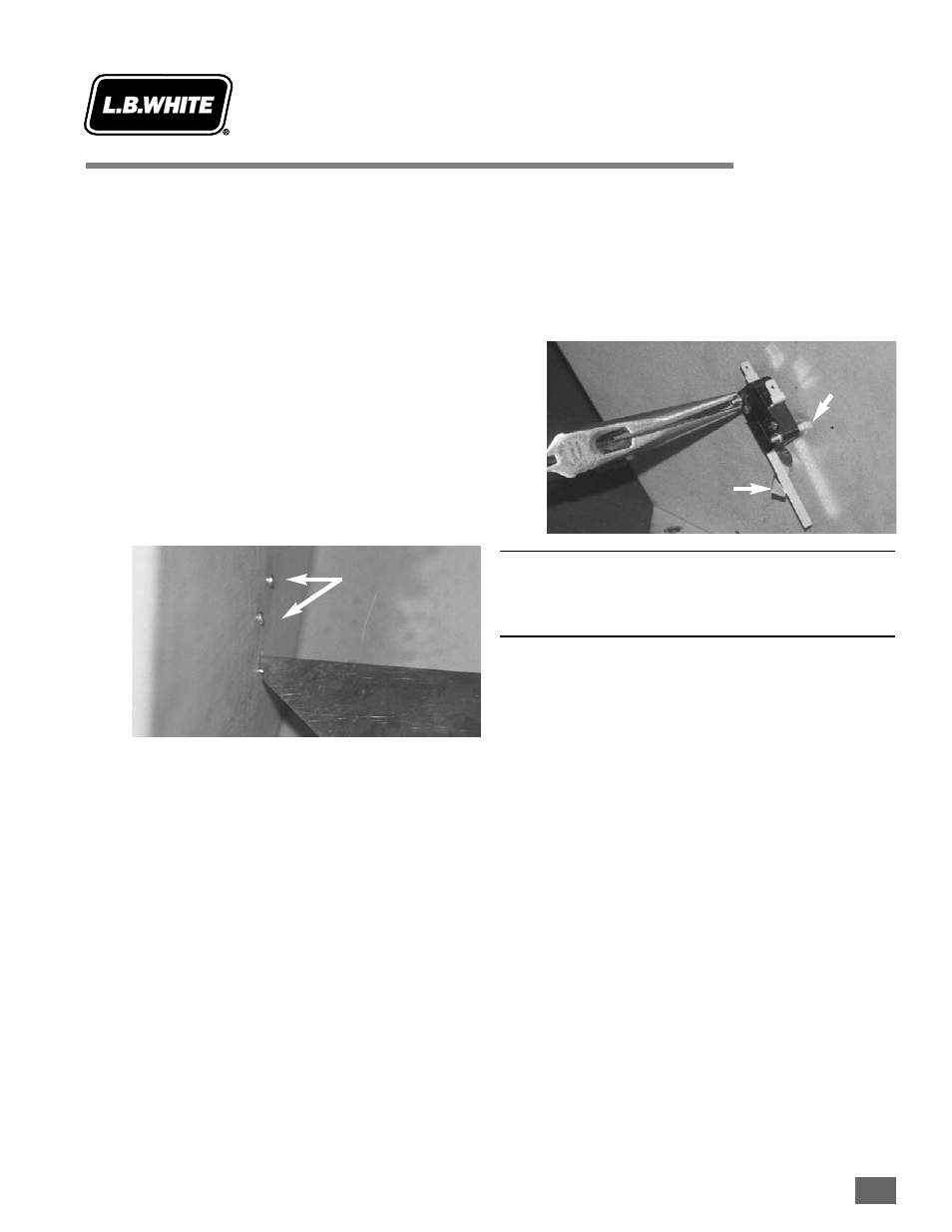
4. The replacement switch will ship with appropriate
quantity of nuts and two screws. Mount the
replacement switch so each mounting screw head is
located inside the fan housing with threads exposed
to the switch side of the housing.
Make sure on reassembly that two nuts per screw are
used as spacers between the switch and housing side
panel. These nuts are tightened securely against the
housing side panel. Slide the switch onto the screws
and secure the switch in place using the two
remaining nuts.
NOTE:
When replacing the switch, make sure the arm of the switch
is located above the flapper arm.
ATTENTION
■
Model 346 heaters do not include air proving
devices.
■
Model AS040 heaters incorporate a centrifugal
switch within the motor to prove that the motor as
turning at proper speed before supplying power to
the gas control valve. The centrifugal switch cannot
be replaced. If it fails, replace the motor.
Air-Proving Switch
Servicing
Instructions
August 1999
Screw H
Heads
Flapper
Two S
Spacer N
Nuts
per S
Screw
Flapper
Arm
8.4-1
1