Servicing instructions – L.B. White Pilot User Manual
Page 55
Component Identification and Function
Servicing
Instructions
All components must work together for proper heater
operation. However, as with anything electrical or
mechanical, problems may arise which will require you to
determine what malfunction has occurred. Before you start
troubleshooting, it’s a good idea to understand the
components in their appearance and purpose.
Main O
Operational C
Components
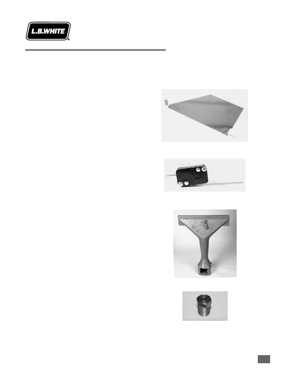
A. Air PProving
A stainless steel flapper (sail) located
Flapper
in the blower outlet that upon an
increase in air pressure generated by
the fan and motor, lifts and pivots
upward and engages the air proving
switch arm, thereby closing the switch
contacts, establishing that the motor is
up to full speed and sufficient airflow is
present.
B. Air PProving
Safety device that proves that proper
Switch
motor speed and airflow is being
achieved before the gas control valve is
opened.
C. Burner
A device designed for the burning of
gas or a gas/air mixture in the
combustion zone.
D. Burner O
Orifice
Metering device which is drilled to a
specific diameter to allow a volume of
gas to be fed through the burner at the
stated manifold pressure (see
dataplate) to achieve proper heat
output.
August 1999
8.1-1
1