Component testing, Thermocouple and power unit tests, Equipment r required – L.B. White Pilot User Manual
Page 50: Here iis h how iit w works
Thermocouple and Power Unit Tests
Component
Testing
Equipment R
Required:
Volt / Ohm Meter with DC Scale
Thermocouple Test Kit, Part Number 500-08506
The thermocouple is used in conjunction with the pilot safety
control valve in supplying pilot gas to the pilot orifice.
Here iis H
How iit W
Works:
A thermocouple converts heat energy into electrical energy.
When the tip of the thermocouple is properly positioned in
the pilot flame, the temperature difference between the hot
and cold junction generates a small amount of electrical
energy in the form of direct current (DC) which is fed into the
spring-loaded power unit within the control valve. The
current holds the power unit open to allow gas to be fed to
the pilot orifice.
As long as the pilot gas stays lit and the pilot flame is
directed to the thermocouple, the thermocouple will
continue to create the small amount of electrical energy
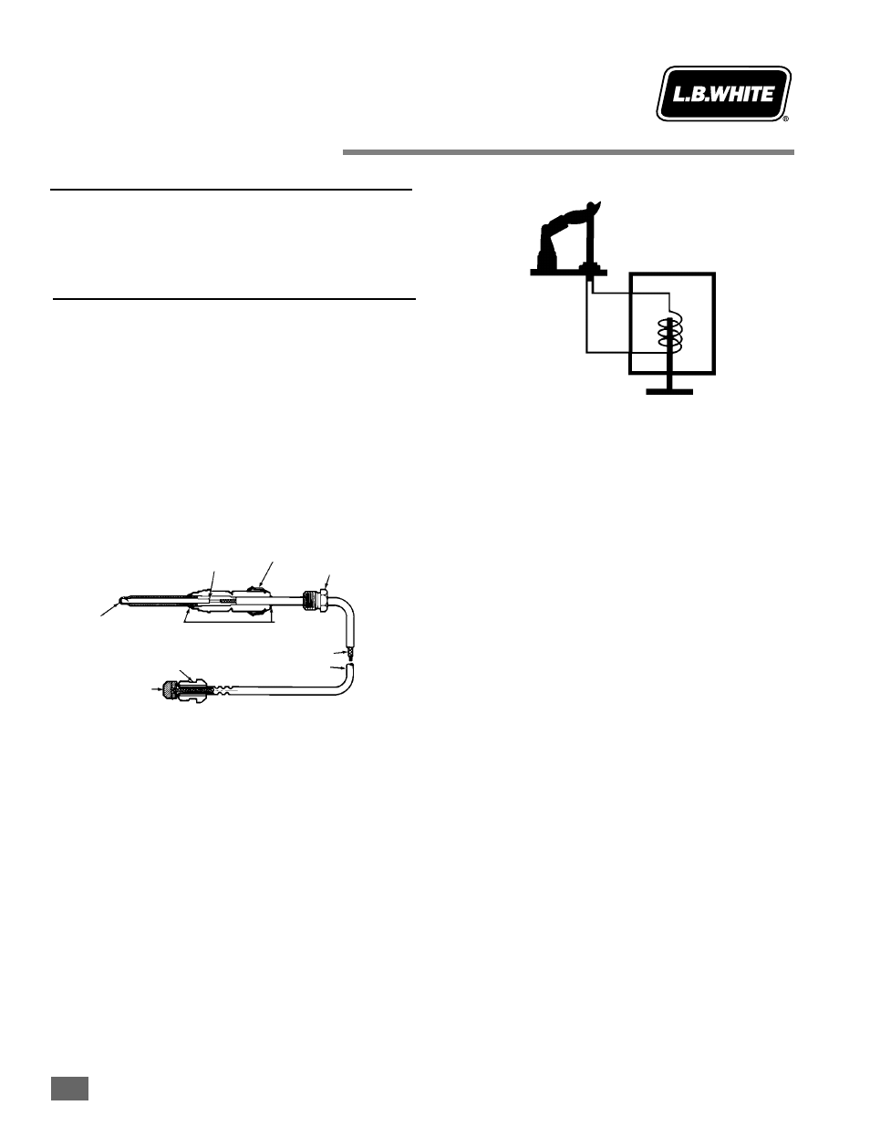
necessary to keep the power unit open. The following
illustration shows the electrical circuit of the thermocouple
with its relationship to the pilot safety control valve.
If the pilot flame is extinguished, or is too small to reliably
heat the thermocouple, the DC output being generated
drops below the minimum level required to hold the power
unit open. The spring within the power unit pushes down the
safety valve plunger, thereby discontinuing the flow of gas to
the pilot and main burner.
If pilot outage problems are occurring, there are several
steps that you must complete before assuming the
thermocouple, or the pilot safety control valve are defective.
These are as follows:
■
Check inlet pressures to the control valve to make sure
the pressure is within parameters specified on the
heater’s dataplate.
■
Clean the pilot assembly components, or if necessary,
replace the pilot orifice if it is plugged.
■
Insure that dirt is not located between the
thermocouple’s power unit contact and power unit
within the safety control valve.
■
Insure that the thermocouple is properly positioned
within the pilot burner bracket, that the pilot flame
envelopes the thermocouple’s tip and the
thermocouple’s contact is snugged at the gas control
valve. (Tighten finger tight plus 1/4 turn.)
■
The pilot shield must be tight against the burner
casting.
■
The pilot gasket (if applicable) is properly installed
between pilot shield and casting.
■
If these items are satisfactory, then proceed to check
both the DC output strength of the thermocouple and
drop-out strength of the electromagnet within the
power unit of the pilot safety control valve.
August 1999
6.3-1
1
PILOT
BURNER
THERMOCOUPLE
SAFETY VVALVE
PLUNGER
THERMOCOUPLE
LEAD
H
HO
OTT JJU
UN
NC
CTTIIO
ON
N
PPO
OW
WEER
R U
UN
NIITT
C
CO
ON
NN
NEEC
CTTO
OR
R
C
CO
ON
NTTAAC
CTT
TTH
HEER
RM
MO
OC
CO
OU
UPPLLEE
C
CO
ON
NN
NEEC
CTTO
OR
R N
NU
UTT
C
CU
UR
RR
REEN
NTT C
CO
ON
ND
DU
UC
CTTO
OR
RS
S
IIN
NS
SU
ULLAATTEED
D W
WIIR
REE
C
CO
OPPPPEER
R TTU
UB
BIIN
NG
G
C
CO
OLLD
D
JJU
UN
NC
CTTIIO
ON
N
O
OPPTTIIO
ON
NAALL
AATTTTAAC
CH
HM
MEEN
NTT
N
NU
UTT
M
MO
OU
UN
NTTIIN
NG
G
C
CLLIIPP
PPO
OW
WEER
R
U
UN
NIITT
C
CO
OIILL