Class1 Valve - 119138 User Manual
Page 13
13
Class 1 Valve Manual
p/n: 119138
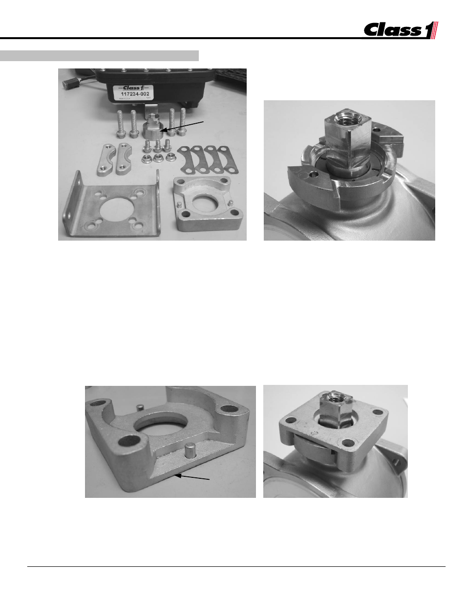
5.4 Electric Actuator Installation
5.4-1 Electric Actuator Assembly Parts
5.4-2 Valve with Stem and Insulator in Place
1. Remove the hex bolt and washer from the valve stem. (These are no longer needed.) Also
remove the stop plate, valve stem retainer (bend if necessary), and wave spring (see valve exploded
view for part details—Section 6.3). Keep the valve stem and valve stem insulator bushing in place.
[Figure 5.4-2]
2. Press the two (2) small dowel pins into the bracket base [Figure 5.4-3], so that they are flush with
the flat side.
3. Place the bracket base onto the top of the valve, aligning the dowel pins with the holes on the
valve. [Figure 5.4-4]
5.4-3 Bracket Base with Dowel Pins
5.4-4 Bracket Base Mounted onto Valve
4. Place the lower bracket on the bracket base. (Orientation of the bracket base affects the orientation of
the electric actuator, and must be determined by the installer.) Insert the four (4) long bolts through
the lower bracket and bracket base. [Figure 5.4-5]
Pins flush
with flat side
Bracket Base
Lower Bracket
Shims
Bottom
Plates
Actuator
Stem Adapter
5. installation