Emi-automatic, Riming, Alve – Hale SPV User Manual
Page 9
S
emi-Automatic
P
riming
V
alve
7
one end of the
7
/
16
-14 x 1-
3
/
4
inch long
studs. Insert studs into the pump body
where the cap screws were removed
then tighten studs.
11. Insert strainer and seal ring in pump
body then install Hale SPV on the pump
body. Make sure the vacuum hose
connection is facing in the down
direction when the Hale SPV is installed.
12. Apply a light coating of thread locking
compound (Loctite #290 or equal) to the
exposed stud threads. Secure Hale SPV
in place using
7
/
16
-14 nuts.
WARNING: Use only pipe, hose, and
fittings from the priming pump vacuum
connection to the Hale SPV vacuum
connection rated for 29 in (737 mm) Hg
vacuum.
13. Attach
3
/
4
inch (19 mm) ID vacuum hose
from the hose connection on the Hale
SPV to the priming pump connection.
Use hose with
3
/
4
inch (19 mm) inside
diameter that is rated for 29 in (737 mm)
Hg vacuum (Aeroquip 2556-12 or equal).
Make sure the hose is routed and
properly secured in place to prevent
chaffing and abraision.
14. Test operation of the Hale SPV and
priming pump. Conduct vacuum and
hydrostatic tests in accordance with
department procedures, NFPA1901 or
NFPA 1911.
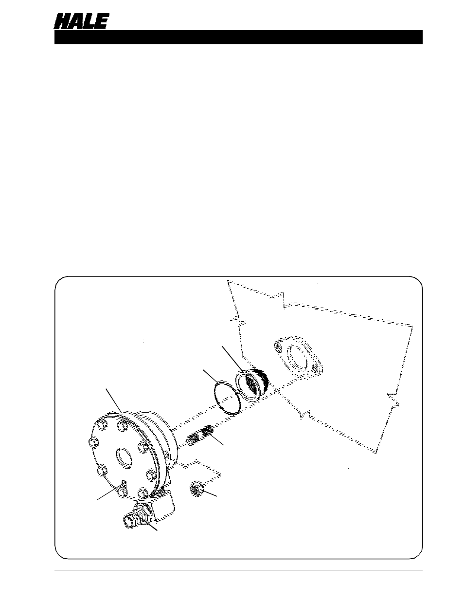
Figure 5. Hale SPV Valve Installation on Midship Fire Pump
MIDSHIP PUMP
BODY (REF.)
HALE SPV
ASSEMBLY
7
/
16
-14 NUT (2)
7
/
16
-14 x 1-
3
/
4
INCH
LONG STUD (2)
PRIMING
STRAINER
SEAL
RING
DIAPHRAGM
COVER
DRAIN
PRIMING HOSE CONNECTION
USE ¾ INCH (19 mm) INSIDE DIAMETER
HOSE