Installation – Hale SPV User Manual
Page 6
S
emi-Automatic
P
riming
V
alve
4
INSTALLATION
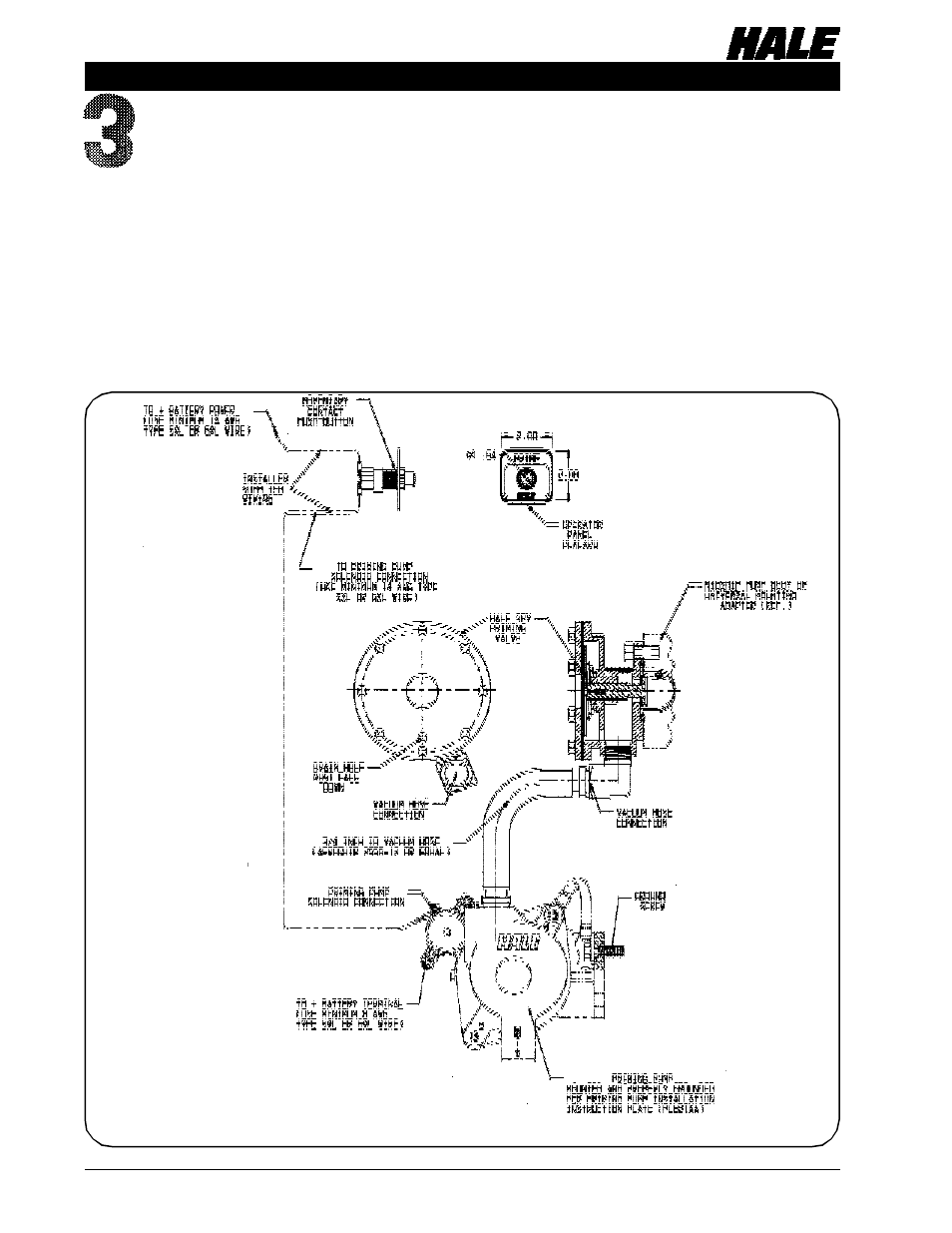
Figure 2. Hale SPV General System Layout Diagram
When ordered as an option on a new midship fire pump the Hale SPV valve assembly is
already attached to the pump body with the vacuum hose connected to the priming
pump when the primer is ordered mounted to the gearbox. All that remains after the
midship pump is mounted on the apparatus frame is to install the panel placard and push-
button on the pump operator panel and make the electrical connections from the switch
to the battery and priming pump solenoid. If the midship pump was ordered with the
primer shipped loose then the primer must be attached to the apparatus and priming
hose must be attached to the Hale SPV hose connection. Figure 2 shows the relative
location of components of the Hale SPV.