Hale MG User Manual
Page 95
Muscle Pumps
5-31
4) Remove the intermediate gear
bearing from the intermediate gear.
5) Remove the two different size
intermediate shaft seal rings from
the intermediate gear shaft.
6) Clean and inspect each
component of the intermediate
shaft assembly. Inspect bearings
for wear, pitting, and damage.
Inspect the gear tooth surface for
wear da mage and pitting, replace
all components that are worn,
damaged, or pitted.
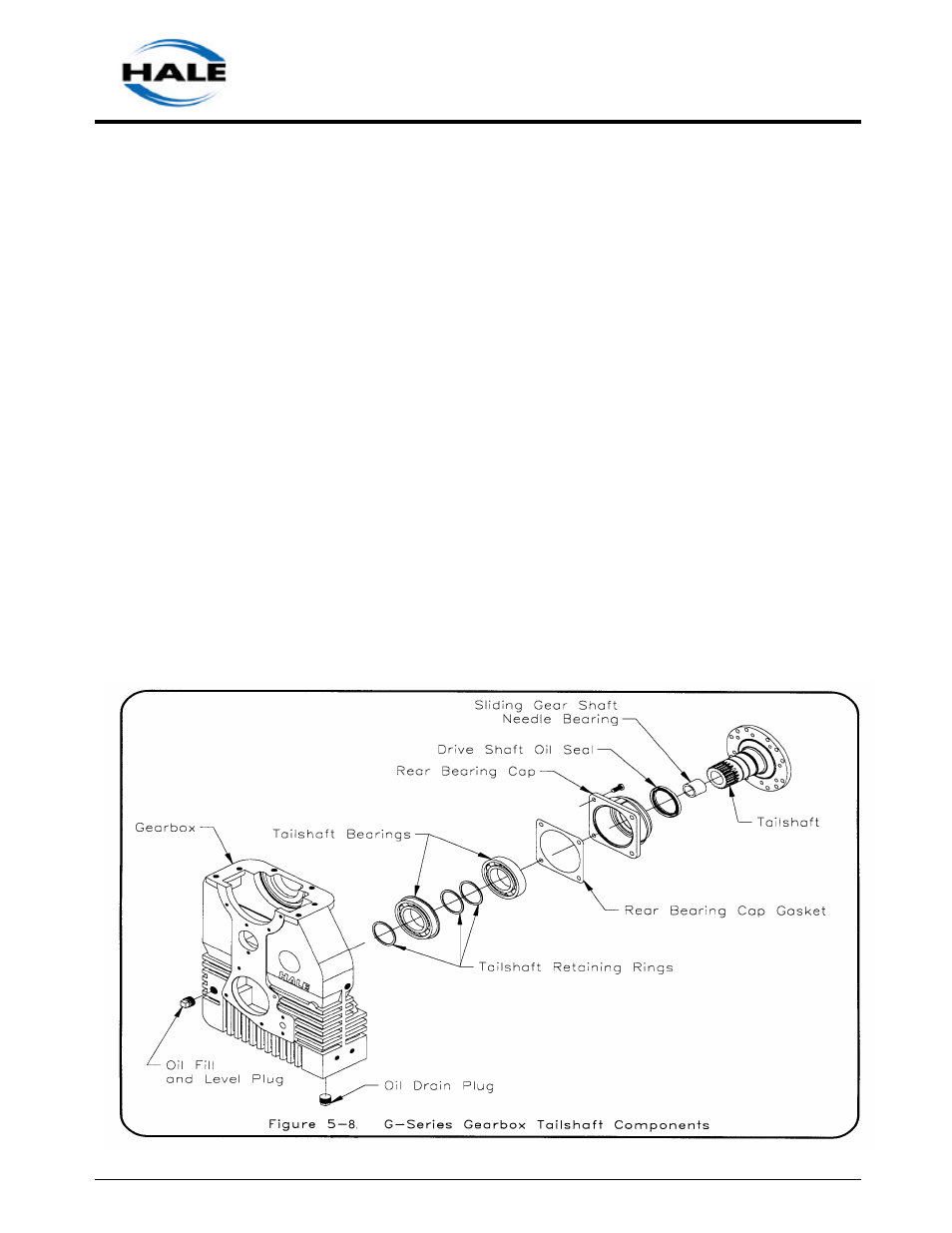
j. Remove and disassemble the tail shaft
assembly (refer to figure 5-8).
NOTE: If the tail shaft and sliding gear shaft
require service it is not necessary to remove the
gearbox from the apparatus.
NOTE: If only the tail shaft assembly needs to be
removed, set the gearshift mechanism to engage
the sliding gear with the sliding gear shaft (pump
position).
1) Loosen the 3/8-16UNC inch hex
nut locking the gearshift rod end
to the gear shaft. Remove the
gearshift rod end with the hex nut.
2) Remove the 1/2-20 UNF X 1/2
inch long nylon loc king set
screw, gearshift lock spring and
gearshift ball from the gearshift
shaft cap.
3) Remove two 5/16-18 hex nuts and
two 5/616-18UNC X 1 inch long cap
screws and remove the cylinder
cover.
4) Remove the outer retaining ring
locking the cylinder piston to the
gearshift shaft
5) Remove the cylinder piston, then
remove the inner retaining ring.
6) Remove two 7/16-14UNC X 1 inch
long nylon locking cap screws and
remove the shifting cylinder.