Hale MG User Manual
Page 55
Muscle Pumps
3-12
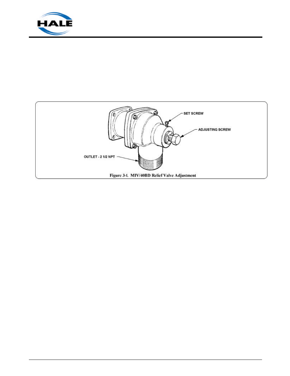
BAR). Test and set relief valve as necessary using
the following procedures and figure 3-1.
1. Open operator panel and gain access to the
relief valve adjustment cap screw.
2. Make sure the valve is closed and install a
pressure test cap on the suction tube or
discharge fitting.
3. Connect a pressurized water source or hydrostatic
test pump and water supply to the pressure test cap
fitting.
4. Open water supply valve and air bleed valve.
Fill suction tube or discharge connection until
water flows from air bleed. Close air bleed.
5. Pressurize to desired set pressure in
accordance with the above warnings. Observe
whether relief valve opens or remains closed at
the desired pressured.
6. Using a 3/16 inch allen wrench loosen, BUT
DO NOT REMOVE, the set screw that locks
the pressure adjustment cap screw.
7. Using 7/8 inch open end wrench, turn pressure
adjustment cap screw to set relief valve
pressure (clockwise to increase opening
pressure or counterclockwise to decrease
opening pressure). Turn cap screw until relief
valve just opens or closes.
Once relief valve opens or closes turn pressure
adjustment cap screw 1/4 turn in the clockwise
(increase pressure) direction.
8. Lock the pressure setting by turning the
adjustment locking screw until tight. Lock
screw in place with Loctite #290 or equivalent.
9. Turn off water source and relieve pressure
through the air bleeder allowing relief valve to
reset.
10. Reenergize water source and return the
pressure to the relief valve set point to verif y
valve-opening point. Repeat adjustment
procedures as necessary to verify relief valve
operation.
11. Open drain valve and drain water from suction
tube or discharge connection.
12. Disconnect water supply and remove test cap
from suction tube or discharge connection.
13. Close operator panel and return apparatus to
normal ready condition.
Worn Clearance Rings and Impeller Hubs
Because clearance ring replacement requires pump
disassembly, it is advisable to thoroughly check
other possible causes (see Table 4-1) of low
performance before assuming that clearance ring
wear is at fault.
Clearance (that is, sealing) rings limit the internal
bypass of water from the discharge side of the
pump back to the suction. The radial clearance
between the impeller hub and the clearance rings is
only a few thousandths of an inch when new,
effectively preventing a large bypass.