Hale MG User Manual
Page 16
Muscle Pumps
1-9
Impeller inlets are on opposite sides of the pump to
balance axial forces; discharges are on opposite
sides to balance radial forces.
Qpak and Qflo Pumps
The Hale Qpak and Qflo pump body is a single
piece. Service of the impeller, clearance rings and
mechanical seal is accomplished by removing the
gearbox and rear pump head/bearing housing from
the pump. This can be accomplished without
disturbing discharge or suction piping attached to
the pump.
The Qpak and Qflo pump has two large suction
inlets on the left and right sides. The incoming
water is directed to the impeller through the
suction passages.
A tank suction valve opening, located on the rear
of the Qpak and Qflo pump allows for high flows
from the booster tank. An optional built-in check
valve is available to prevent tank over-
pressurization.
Hale muscle pumps are “manifolded” type pumps
meaning the pump volute, suction manifolding,
and discharge manifolding are cast as one piece.
This one-piece pump design simplifies installation
of the pump and plumbing of the discharge piping.
Discharge valves in the basic pump configuration
can be mounted at either side of the pump body.
However, the manifolded pump body provides
several additional discharge locations (facing front,
back, or up) that can accommodate additional
discharge valves.
Impeller
The impeller provides velocity to the water. This
part is mounted on a shaft that is rotated by the
drive. Water enters the rotating impeller at the
intake (or eye), and is confined by the shrouds and
the vanes mounted in the impeller to build
pressure. The vanes guide water from the inlet to
the discharge and reduce the turbulence of the
spinning water. Vanes curve away from the
direction of rotation so water moves toward the
outer edge. The shrouds form the sides of the
impeller, and keep the water confined to
centrifugal acceleration.
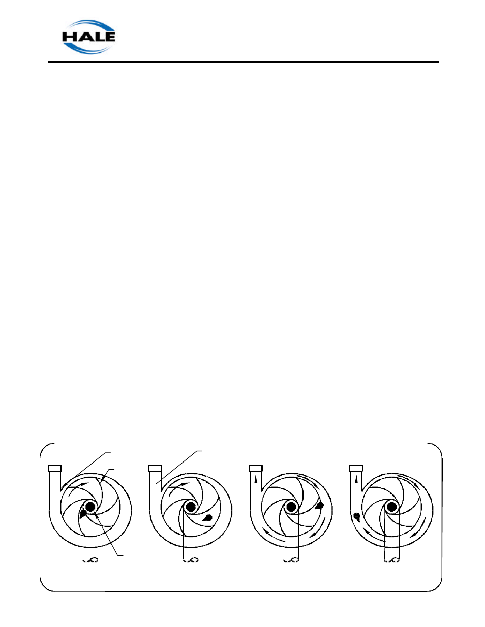
Figure 1-8 traces a drop of water from the intake of
the impeller to the discharge outlet. The impeller is
mounted so that the discharging tube is widest at
the pump outlet. The increasing discharge path,
known as the volute, collects the water at a
constant velocity. A further increase in pressure
and a decrease in velocity take place in the
diffuser.
Clearance Rings
Clearance rings prevent the water that is
pressurized and leaving the pump volute from
returning to the intake of the impeller. Centrifugal
pumps have clearance rings at the impeller intake
to prevent leakage. This is accomplished by limiting
the radial clearance between the spinning impeller
and the stationary clearance ring. Refer to figure 1-7.
Figure 1-8. Impeller Operation
INTAKE
DISCHARGE
CUT WATER
EYE
VANES
DIFFUSER