Pump body/impeller, Pump body disassembly, Figure 15: pump body and impeller assembly – Hale 4DK Series User Manual
Page 32: Impeller disassembly
32
Manual p/n: 029-0020-79-0
4DK Series Pumps
PUMP BODY/IMPELLER
To service the internal parts of the gearbox or
pump head (pump shaft, bearings, seals, impel-
ler, etc.) the pump body must first be removed.
See Figure 15: "Pump Body and Impeller
Assembly."
Note: The pump body can be removed while
the pump and gearbox assembly are mounted
on the apparatus.
CAUTION !
BEFORE WORKING ON THE PUMP, DISCONNECT
SUCTION AND DISCHARGE PIPING AND DRAIN
THE PUMP BODY.
Pump Body Disassembly
See Figure 15: "Pump Body and Impeller
Assembly."
1. Drain the inlet (suction) side of the pump
body per your required procedures. Then
disconnect the suction and discharge lines.
2. Remove the 1/4" NPT pipe plug from the
pump body to drain any remaining fluid.
Have a suitable container available to
collect access fluid, approximately one to
two gallons (3.8-7.6 liters).
3. Remove twelve 7/16-14 x 1-1/4" cap
screws and washers that secure the pump
body to the pump head.
4. Slide the pump body from the pump head
assembly being careful not to damage the
pump shaft or mechanical seal assembly.
If you are servicing the mechanical seal,
see heading "Mechanical Seal Assembly"
on page 34.
5. Scrape all remaining gasket material from
the pump head and mating surfaces being
careful not to score the machined surfaces.
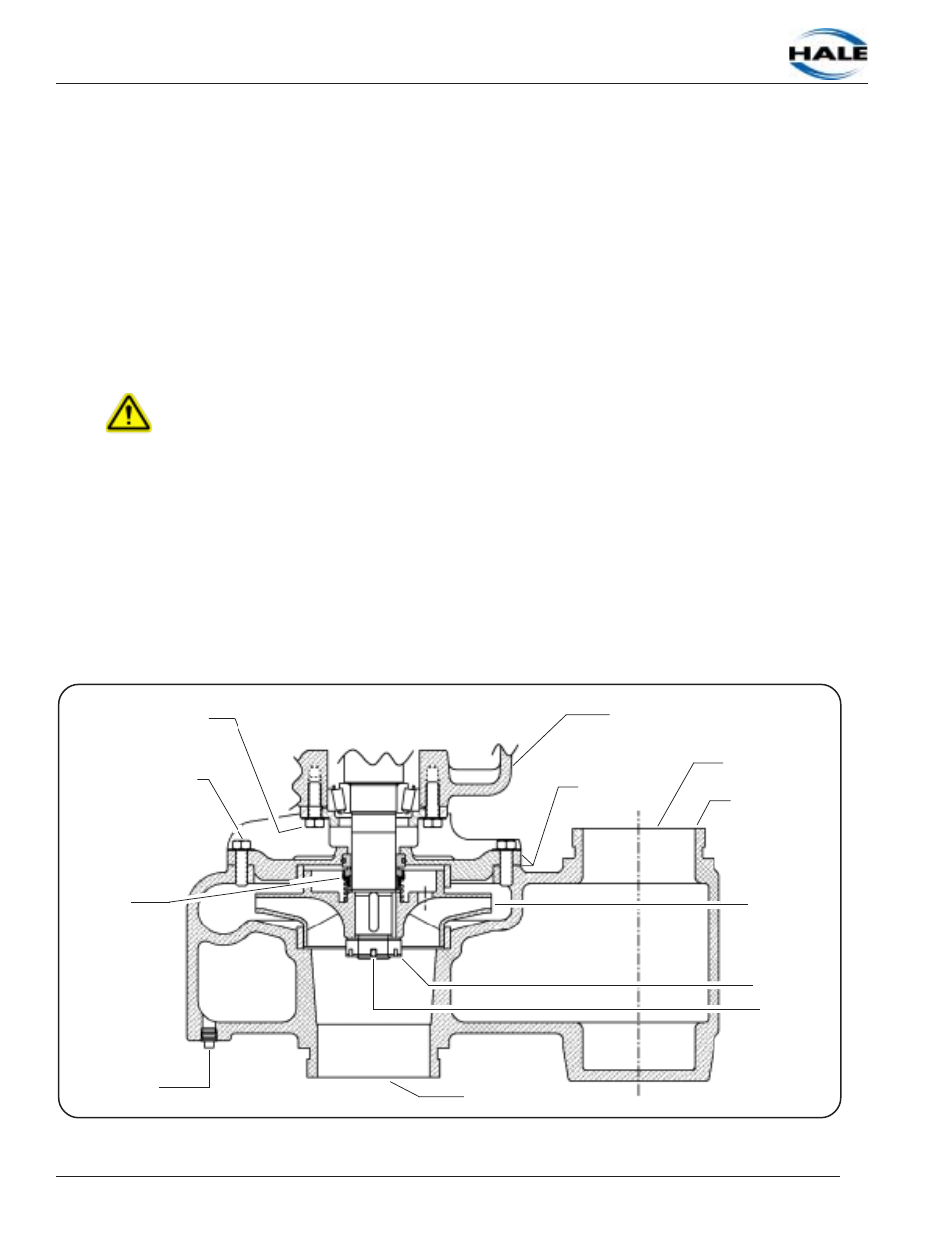
Figure 15: Pump Body and Impeller Assembly
Pump Body
Pump Housing/Gearbox
Screws / Washers (12)
7/16-14 x 1-1/4"
Screws / Washers (4)
7/16-14 x 1-1/4"
Pump Head and
Gasket
Impeller
Impeller
Nut
Spring Pin
Plug
Mechanical
Seal
Pump Discharge
Pump Inlet (Suction)