Inspection, Installation, Figure 14: idler shaft assembly – Hale 4DK Series User Manual
Page 31: Pump body/impeller
Manual p/n: 029-0020-79-0
31
4DK Series Pumps
Inspection
See Figure 14: "Idler Shaft Assembly."
1. Clean bearings and other components
using parts cleaner.
2. Carefully inspect bearings and seals for
signs of excessive wear.
The bearings, shims, and spacers are a
matched set and must be replaced as a
unit. Order a new set using Hale p/n: 250-
8270-50-0.
3. Obtain new components from Hale Prod-
ucts as appropriate.
Installation
See Figure 14: "Idler Shaft Assembly."
1. Assemble the idler gear assembly by first
installing the two retaining rings into the
idler gear using retaining ring pliers.
2. Next press the bearing cups into the idler
gear.
3. Finish the assembly by installing the
bearing spacer, shims, and cones.
4. Install the O-ring on the idler shaft.
5. With the gearbox housing horizontal,
partially insert the idler shaft into the
housing, and slide the idler gear assembly
and spacer onto the shaft.
6. Apply Loctite 246 (or equal) to the 1/2-13 x
1-1/2" screw and brass washer.
Tighten screw to 75 ft.-lb. (102 N-m). This
will pull the shaft into the housing.
7. Install the input shaft, KPS, tail shaft, and
gearbox cover.
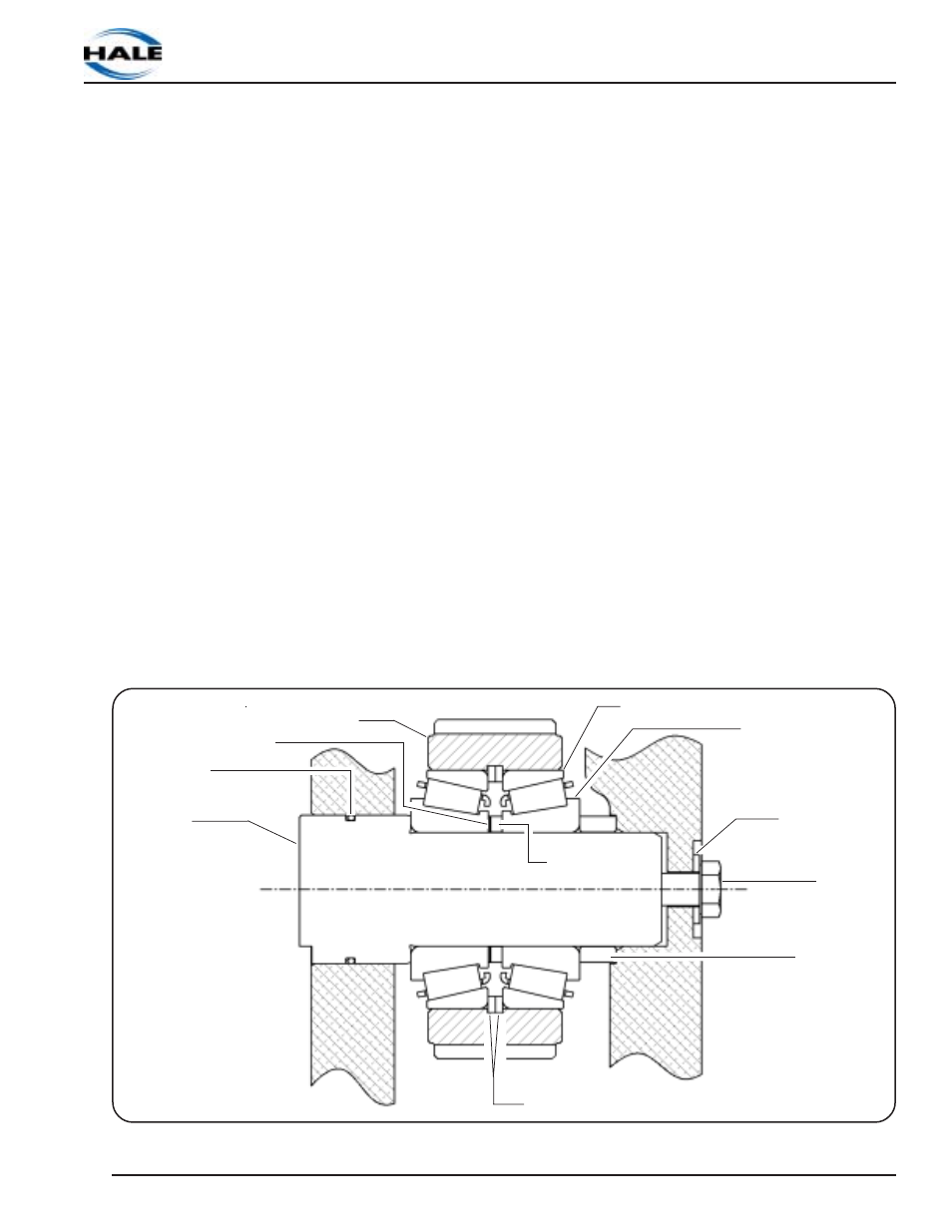
Figure 14: Idler Shaft Assembly
Idler
Shaft
O-Ring Seal
Idler
Gear
Shims
Bearing Cups
Bearing Cones
Shims
Washer
Spacer
Nut
1/2-13 x 1-1/2"
Retaining Rings (2)