Input shaft, Removal and disassembly, Figure 10: input shaft assembly – Hale 4DK Series User Manual
Page 26
26
Manual p/n: 029-0020-79-0
4DK Series Pumps
Rotate the yoke to ensure free spin. If too
tight, back-off slightly on the 3/4-10 bolt.
15. Secure the bearing carrier using eight
7/16-14 x 1-1/2" screws. Apply Loctite 246
(or equal) to the threads prior to installa-
tion. Torque screws to 50 ft.-lb (68 N-m).
16. Replace the fluid and install the gearbox
cover.
INPUT SHAFT
See Figure 10: "Input Shaft Assembly."
Removal and Disassembly
1. Remove gearbox cover and tail shaft
assembly as previously described.
2. Unscrew the 3/4-10 x 1-3/4" bolt and
washer securing the input yoke.
Slide the yoke off the input shaft.
3. Carefully drive the input shaft into the
gearbox using a dead blow hammer, or
similar, to avoid marring the shaft.
4. Pull the input shaft through the bearing
carrier bore and out of the gearbox
housing.
The shift collar, input gear, bearing cone,
inner spacer, shims, needle bearing, and
bearing cup may drop into the gearbox
housing. Remove these components from
the gearbox housing.
5. If necessary, remove the roller bearing
outer race from the input shaft.
6. Remove the oil seal. It will be damaged
during this process and must be replaced.
A replacement oil seal can be ordered
using Hale p/n: 296-2860-01-0.
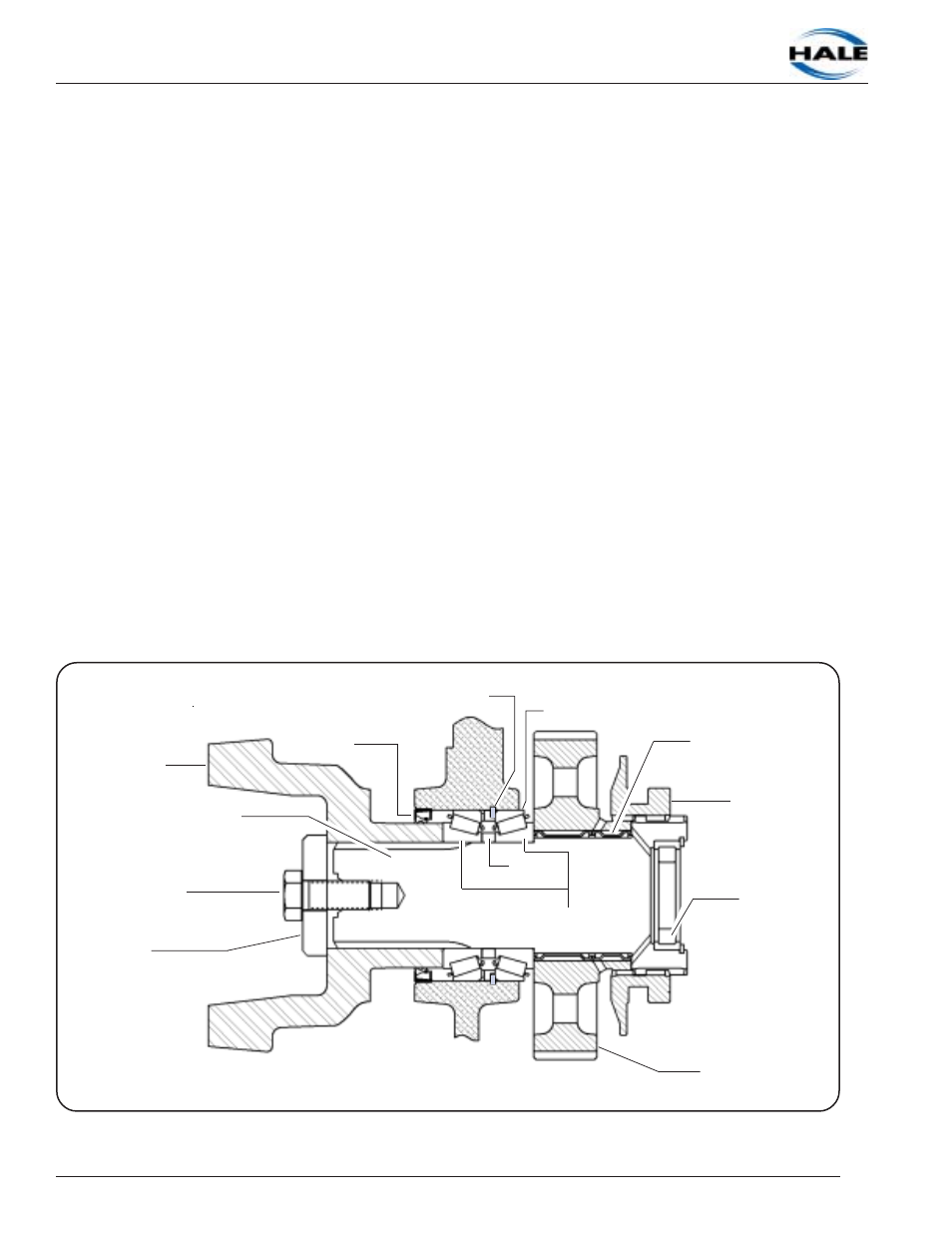
Figure 10: Input Shaft Assembly
Yoke
Screw
3/4-10 x 1-3/4"
Washer
Input Shaft
Oil Seal
Shims
Bearing Cups
Retainer Ring
Bearing Cones
Needle Bearing
Shift Fork
Roller Bearing
Outer Race
Input Gear