Bryant DURAPACK 558F User Manual
Page 4
—
4
—
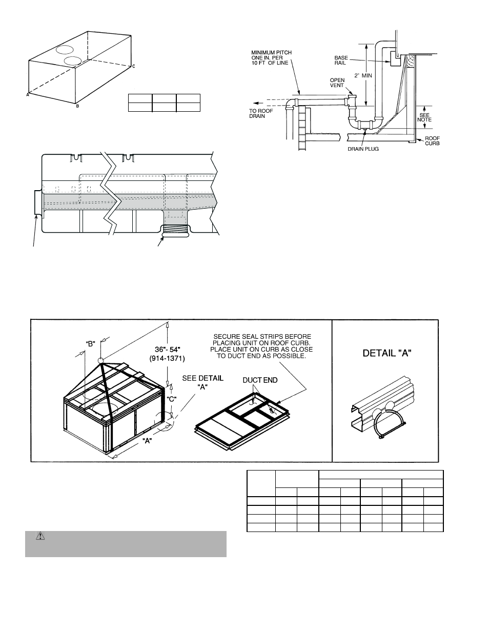
MAXIMUM ALLOWABLE
DIFFERENCE (in.)
A-B
B-C
A-C
0.5
1.0
1.0
Fig. 3 — Unit Leveling Tolerance
NOTES:
1. Dimension in ( ) is in millimeters.
2. Hook rigging shackles through holes in base rail, as shown in detail
‘‘A.’’ Holes in base rails are centered around the unit center of grav-
ity. Use wooden top skid when rigging to prevent rigging straps
from damaging unit.
3. Unit weights do not include economizer. See Tables 1A and 1B for
unit weight of economizer.
CAUTION:
All panels must be in place when rigging. Unit
is not designed for handling by a fork truck. Damage to unit may
result.
UNIT
558F
OPERATING
WEIGHT
DIMENSIONS
‘‘A’’
‘‘B’’
‘‘C’’
lb
kg
in.
mm
in.
mm
in.
mm
090,091
755
342
77.42 1967 40.25 1022 41.31 1050
102,103
760
345
77.42 1967 40.25 1022 41.31 1050
120,121
915
415
77.42 1967 40.25 1022 49.31 1253
150,151
930
422
77.42 1967 40.25 1022 49.31 1253
Fig. 6 — Rigging Details
DRAIN PLUG
HORIZONTAL
DRAIN OUTLET
NOTE: Drain plug is shown in factory-installed position.
Fig. 4 — Condensate Drain Connection (Side View)
NOTE: Trap should be deep enough to offset maximum unit static differ-
ence. A 4-in. trap is recommended.
Fig. 5 — Condensate Drain Piping Details