Bryant DURAPACK 558F User Manual
Page 23
—
23
—
C. Optional EconoMi$er IV
See Fig. 17 for EconoMi$er IV component locations.
NOTE: These instructions are for installing the optional
EconoMi$er IV only. Refer to the accessory EconoMi$er IV
installation instructions when field installing an EconoMi$er IV
accessory.
1. To remove the existing unit filter access panel, raise
the panel and swing the bottom outward. The panel is
now disengaged from the track and can be removed.
See Fig. 18.
2. The box with the economizer hood components is
shipped in the compartment behind the economizer.
The EconoMi$er IV controller is mounted on top of
the EconoMi$er IV in the position shown in Fig. 17.
To remove the component box from its shipping posi-
tion, remove the screw holding the hood box bracket
to the top of the economizer. Slide the hood box out of
the unit. See Fig. 19.
IMPORTANT: If the power exhaust accessory is to be
installed on the unit, the hood shipped with the unit will not
be used and must be discarded. Save the aluminum filter
for use in the power exhaust hood assembly.
3. The indoor coil access panel will be used as the top of
the hood. Remove the screws along the sides and bot-
tom of the indoor coil access panel. See Fig. 20.
4. Swing out indoor coil access panel and insert the
hood sides under the panel (hood top). Use the screws
provided to attach the hood sides to the hood top. Use
screws provided to attach the hood sides to the unit.
See Fig. 21.
5. Remove the shipping tape holding the economizer
barometric relief damper in place.
6. Insert the hood divider between the hood sides. See
Fig. 21 and 22. Secure hood divider with 2 screws on
each hood side. The hood divider is also used as the
bottom filter rack for the aluminum filter.
7. Open the filter clips which are located underneath
the hood top. Insert the aluminum filter into the bot-
tom filter rack (hood divider). Push the filter into
position past the open filter clips. Close the filter clips
to lock the filter into place. See Fig. 22.
8. Caulk the ends of the joint between the unit top panel
and the hood top. See Fig. 20.
SCREWS
(SIDE)
MANUAL
OUTDOOR-AIR
ADJUSTMENT
SCREWS
DAMPER
BLADE
FILTER
ACCESS
PANEL
OUTDOOR AIR
OPENING
PANEL
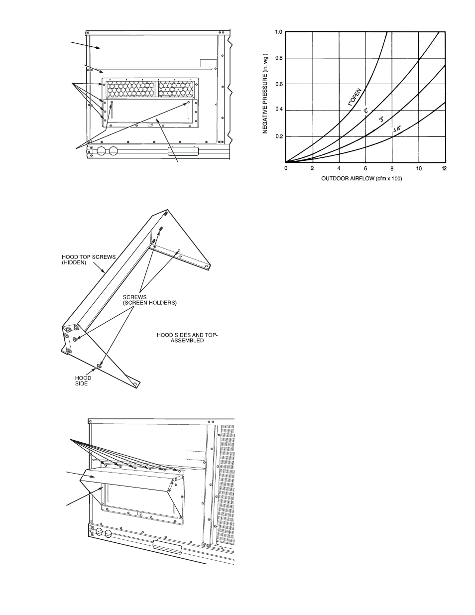
Fig. 13 — Damper Panel with Manual
Outdoor-Air Damper Installed
Fig. 14 — Outdoor-Air Hood Details
SCREW
HOLES
(TOP)
HOOD
HOOD
SCREEN
LOCATION
(SCREEN
NOT
SHOWN)
Fig. 15 — Optional Manual Outdoor-Air
Damper with Hood Attached
Fig. 16 — Outdoor-Air Damper Position Setting