Bryant DURAPACK 558F User Manual
Page 21
—
21
—
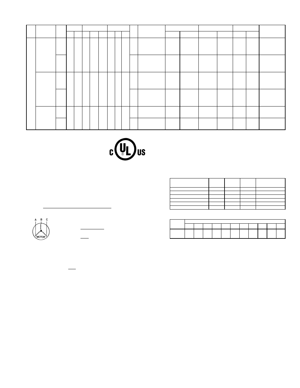
Table 2D — Electrical Data (Units With Convenience Outlet) (558F091, 103, 121, 151) (cont)
LEGEND
*Used to determine minimum disconnect per NEC.
†Fuse or HACR circuit breaker per NEC.
**Fuse only.
††Compressor no. 1 is shown in table.
208/230-3-60: Compressor no. 2 RLA is 14.1 amps and LRA is 105 amps.
460-3-60: Compressor no. 2 RLA is 7.1 amps and LRA is 55 amps.
575-3-60: Compressor no. 2 RLA is 6.4 amps and LRA is 40 amps.
NOTES:
1.
In compliance with NEC requirements for multimotor and combination load equipment (refer to NEC
Articles 430 and 440), the overcurrent protective device for the unit shall be fuse or HACR breaker.
Canadian units may be fuse or circuit breaker.
2.
Unbalanced 3-Phase Supply Voltage
Never operate a motor where a phase imbalance in supply voltage is greater than 2%. Use the
following formula to determine the percent of voltage imbalance.
% Voltage Imbalance
Example: Supply voltage is 460-3-60.
AB = 452 v
BC = 464 v
AC = 455 v
= 457
Determine maximum deviation from average voltage.
(AB) 457 – 452 = 5 v
(BC) 464 – 457 = 7 v
(AC) 457 – 455 = 2 v
Maximum deviation is 7 v.
Determine percent of voltage imbalance.
= 1.53%
This amount of phase imbalance is satisfactory as it is below the maximum allowable 2%.
IMPORTANT: If the supply voltage phase imbalance is more than 2%, contact your local electric utility
company immediately.
3. For units with power exhaust: If a single power source is to be used, size wire to include power
exhaust MCA and MOCP. Check MCA and MOCP when power exhaust is powered through the
unit (must be in accordance with NEC and/or local codes). Determine the new MCA including the
power exhaust using the following formula:
MCA New = MCA unit only + MCA of Power Exhaust
For example, using a 558FPX091000 unit with MCA = 40.1 and MOCP = 45, with
CRPWREXH030A01 power exhaust.
MCA New = 40.1 amps + 1.6 amps = 41.7 amps
If the new MCA does not exceed the published MOCP, then MOCP would not change. The MOCP
in this example is 45 amps, the MCA New is below 45, therefore the MOCP is acceptable. If “MCA
New” is larger than the published MOCP, raise the MOCP to the next larger size. For separate
power, the MOCP for the power exhaust will be 15 amps per NEC.
4. Determine heater capacity using multiplication factors table below:
NOTE: The following equation converts kW of heat energy to Btuh: kW x 3.412 = Btuh.
EXAMPLE: 32.0 kW (at 240 v) heater on 208 v
= 32.0 (.751 mult factor)
= 24.0 kW capacity at 208 v
558F
UNIT
SIZE
NOMINAL
V-PH-Hz
IFM
TYPE
VOLTAGE
RANGE
COMPRESSOR
(ea)
OFM (ea)
IFM
FLA
HEATER
MODEL NO.
CRHEATER---A00
ELECTRIC HEAT
POWER SUPPLY
DISCONNECT
SIZE*
SINGLE POINT
BOX P/N
CRSINGLE---A00
Min
Max
Qty
RLA
LRA
Qty
Hp
FLA
Nominal
kW
FLA
MCA
MOCP†
FLA
LRA
151
208/230-3-60
STD
187
254
2
19
156
2
1
/
4
1.4
10.6
NONE
—/—
—/—
61.0/ 61.0
70/ 70**
65/ 65
364/364
—
017
7.8/10.4
21.7/ 25.0
61.0/ 61.0
70/ 70**
65/ 65
364/364
012
010
12.0/16.0
33.4/ 38.5
61.0/ 66.8
70/ 70**
65/ 65
364/364
012
012
24.0/32.0
66.7/ 77.0
102.6/114.9
110/125**
94/106
364/364
012
012 and 017
31.8/42.4
88.4/102.0
129.7/146.2
150/150**
119/135
364/364
015
010 and 012
37.6/50.0
104.2/120.3
149.6/169.0
150/175**
138/156
364/364
015
ALT
15
NONE
—/—
—/—
65.4/ 65.4
80/ 80**
70/ 70
383/383
—
017
7.8/10.4
21.7/ 25.0
65.4/ 65.4
80/ 80**
70/ 70
383/383
012
010
12.0/16.0
33.4/ 38.5
66.5/ 72.3
80/ 80**
70/ 70
383/383
012
012
24.0/32.0
66.7/ 77.0
108.1/120.4
110/125**
99/111
383/383
012
012 and 017
31.8/42.4
88.4/102.0
135.2/151.7
150/175**
124/140
383/383
015
010 and 012
37.6/50.0
104.2/120.3
155.1/174.5
175/175**
143/161
383/383
015
460-3-60
STD
414
508
2
9
75
2
1
/
4
0.7
4.8
NONE
—
—
28.7
35
30
176
—
013
16.5
19.8
33.5
35
31
176
011
014
27.8
33.4
47.8
45
46
176
011
015
33.0
39.7
58.3
60
54
176
011
014 and 016
41.7
50.2
71.4
80**
66
176
014
013 and 015
50.0
60.1
83.9
90**
77
176
014
ALT
7.4
NONE
—
—
31.3
35
33
215
—
013
16.5
19.8
36.8
40
34
215
011
014
27.8
33.4
51.0
60
49
215
011
015
33.0
39.7
61.6
70**
57
215
014
014 and 016
41.7
50.2
74.7
80**
69
215
014
013 and 015
50.0
60.1
87.1
90**
80
215
014
575-3-60
STD
518
632
2
7.4
54
2
1
/
4
0.7
4.8
NONE
—
—
23.3
30
25
129
—
018
17.0
17.1
28.3
30
26
129
011
019
34.0
34.1
49.6
45
46
129
011
018 and 019
51.0
51.2
71.0
80**
65
129
014
ALT
7.4
NONE
—
—
25.4
30
27
160
—
018
17.0
17.1
30.9
35
28
160
011
019
34.0
34.1
52.2
50
48
160
011
018 and 019
51.0
51.2
73.6
80**
68
160
014
FLA
—
Full Load Amps
HACR
—
Heating, Air Conditioning and Refrigeration
IFM
—
Indoor (Evaporator) Fan Motor
LRA
—
Locked Rotor Amps
MCA
—
Minimum Circuit Amps
MOCP
—
Maximum Overcurrent Protection
NEC
—
National Electrical Code
OFM
—
Outdoor (Condenser) Fan Motor
RLA
—
Rated Load Amps
= 100 x
max voltage deviation from average voltage
average voltage
Average Voltage =
452 + 464 + 455
3
=
1371
3
% Voltage Imbalance = 100 x
7
457
POWER EXHAUST
PART NO.
MCA
(230 v)
MCA
(460 v)
MCA
(575 v)
MOCP
(for separate
power source)
CRPWREXH021A01
N/A
0.9
N/A
15
CRPWREXH022A01
3.3
N/A
1.32
15
CRPWREXH023A01
N/A
1.8
N/A
15
CRPWREXH028A01
1.7
N/A
0.68
15
CRPWREXH029A01
N/A
1.0
N/A
15
CRPWREXH030A01
1.6
N/A
0.64
15
HEATER
RATING
VOLTAGE
ACTUAL HEATER VOLTAGE
200
208
230
240
380
440
460
480
550
575
600
240
0.694 0.751
0.918 1.000
—
—
—
—
—
—
—
480
—
—
—
—
0.626 0.840 0.918
1.000
—
—
—
600
—
—
—
—
—
—
—
—
0.840
0.918 1.000