Bunn Dual TF User Manual
Page 27
Page 27
SERVICE (cont.)
LEVEL CONTROL BOARD AND LEVEL PROBE
(Electro/mechanical only) (cont.)
els and three wire 120/240 volt models.
b.) 200 to 240 volts ac for two wire 200 or 240 volt
models.
17. Disconnect the brewer from the power source.
If voltage is present as described, reinstall the probe,
the level control board and level probe are operating
properly.
If voltage is not present as described, check the pink
probe wire for continuity.
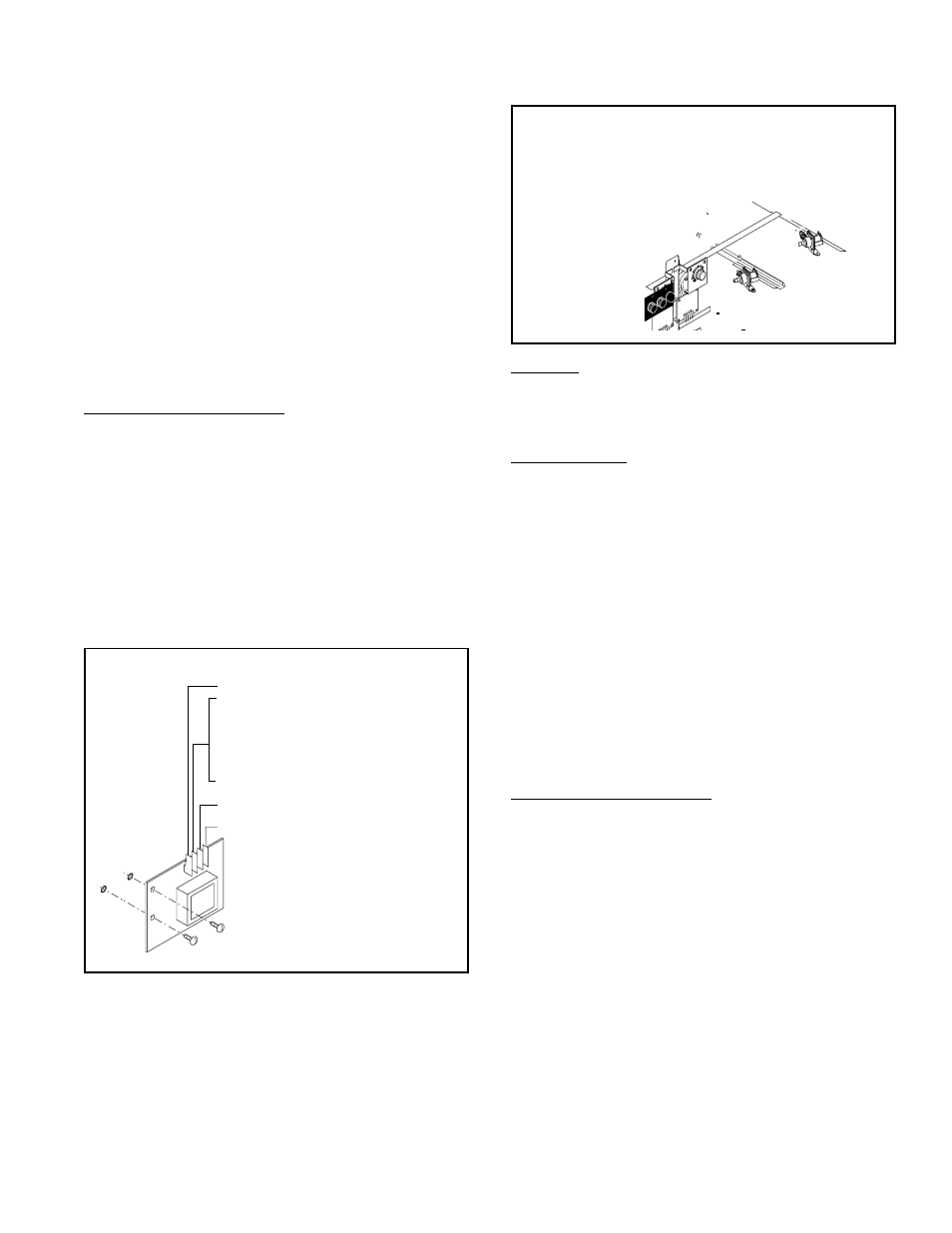
Removal and Replacement:
1. Remove all wires from the level control board.
2. Remove two #8-32 slotted head screws holding
level control board to component bracket.
3. Install the new level control board to the compo-
nent bracket. Make certain that the lockwashers
are between the level control board and the com-
ponent bracket.
4. Refer to the illustration below when reconnecting
the wires.
T1 VIO to Solenoid Coil
T2 BLU to Overflow Protection Switch
T3 WHI to Terminal Block (White Insert
on 120V Two Wire , 120/208V or 120/240V
Three Wire Brewers)
T3 RED to Terminal Block (Red Insert on
200V or 240V Brewers)
T4 PNK to Probe
Location:
The limit thermostat is located inside the hood
on the tank lid just to the left of the right tank heater.
Test Procedure:
1. Disconnect the brewer from the power supply.
2. Disconnect the black wires from the limit thermo-
stat.
3. Check continuity across the limit thermostat ter-
minals with an ohm meter
If continuity is present as described, reconnect the
black wires to the limit thermostat, the limit thermo-
stat is operating properly.
If continuity is not present as described, press the
reset button on the limit thermostat and repeat step
#3. After repeating step #3 no continuity is shown,
replace the limit thermostat.
Removal and Replacement:
1. Remove all wires from the limit thermostat termi-
nals.
2. Carefully remove the two #8-32 nuts securing the
limit thermostat to tank lid and remove limit ther-
mostat.
3. Carefully secure new limit thermostat to tank lid.
4. Refer to the illustrations below when reconnecting
the wires.
LIMIT THERMOSTAT
P789
P979
.
MI
NU
TE
S
BU
NN
-O
-M
AT
IC
P/
N
26
20
-
12
0 V
AC
.
MI
NU
TE
S
BU
NN
-O
-M
AT
IC
P/
N
26
20
-
12
0 V
AC
2
2
2
1.5
1.5
1
1
1
.5
.5
2.5
2.5
MI
NU
TE
S
MINUTES
MI
NU
TE
S
MINUTES
MI
NU
TE
S
MINUTES
P/
N
24
48
6-0
00
0
12
0 V
AC
P/N 24486-0000 120 VAC
BU
NN
-O
-M
AT
IC
BUNN-O-MATIC
3
3
3
4
4
5
5
6
6
7
8