Bryant 352MAV User Manual
Page 7
B.
Secondary Heat Exchangers
NOTE:
The condensing side (inside) of the secondary heat
exchangers CANNOT be serviced or inspected. A small number of
bottom outlet openings can be inspected by removing the inducer
assembly. See Flushing Collector Box and Drainage System
section for details on removing inducer assembly.
V.
FLUSHING COLLECTOR BOX AND DRAINAGE SYS-
TEM
1. Turn off gas and electrical supplies to furnace.
2. Remove main furnace door.
3. Disconnect inducer motor and pressure switch wires or
connectors.
4. Disconnect pressure switch tubes.
5. Disconnect vent pipe from inducer housing outlet by
loosening coupling clamp on inducer outlet.
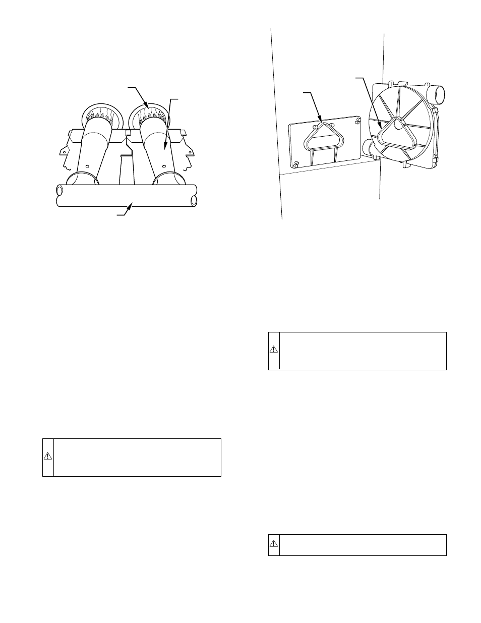
6. Disconnect drain tube from inducer housing. (See Fig. 8.)
7. Remove inducer housing assembly by removing 4 bolts
attaching assembly to cell panel.
8. Flush inside of collector box with water until discharge
from condensate trap is clean and runs freely.
NOTE:
Ensure the drain tube disconnected from the inducer
housing is higher than the collector box opening or water will flow
out tube.
9. Inspect inside area of collector box for any pieces of foreign
materials and remove if present.
CAUTION:
DO NOT use wire brush or other sharp
object to inspect or dislodge materials in secondary heat
exchangers as failure of the secondary heat exchanger
will occur. Flush with water only.
10. Reassemble inducer assembly by reversing items 5-7.
Tighten vent coupling clamp screw(s) to 15 in.-lb of torque.
NOTE:
If seal between the inducer housing and the collector box
is damaged in any way, it must be repaired. To repair, apply
sealant releasing agent such as PAM cooking spray or equivalent
(must not contain corn or canola oil, aromatic or halogenated
hydrocarbons or inadequate seal may occur) to inducer housing.
(See Fig. 10.) Apply a small bead of G.E. RTV 162, G.E. RTV
6702, or Dow-Corning RTV 738 sealant to groove in collector
box.
11. Refer to furnace wiring diagram and reconnect wires to
inducer motor and pressure switches or connectors.
12. Reconnect pressure tubes to pressure switches. See diagram
on main furnace door for proper location of tubes. Be sure
tubes are not kinked. (See Fig. 8.)
13. Turn on gas and electrical supplies to furnace.
14. Check furnace operation through 2 complete heat operating
cycles. Check area below inducer housing, vent pipe, and
condensate trap to ensure no condensate leaks occur. If
leaks are found, correct the problem.
15. Check for gas leaks.
WARNING:
Never use matches, candles, flame, or
other sources of ignition to check for gas leakage. Use a
soap-and-water solution. Failure to follow this warning
could result in a fire, personal injury, or death.
16. Replace main furnace door.
VI.
SERVICING HOT SURFACE IGNITOR
The ignitor does NOT require annual inspection. Check ignitor
resistance before removal.
1. Turn off gas and electrical supplies to furnace.
2. Remove main furnace door.
3. Disconnect ignitor wire connection.
4. Check ignitor resistance.
a. Using an ohm meter, check resistance across both ignitor
leads in connector.
b. Cold reading should be between 45 ohms and 90 ohms.
c. If ohm reading is higher than 110 ohms, ignitor is
cracked and must be replaced.
5. Remove ignitor assembly.
CAUTION:
Allow ignitor to cool before removal. Nor-
mal operation temperatures exceed 2000°.
a. Do not remove ignitor from bracket while assembly is in
furnace. Using a 1/4 in. nutdriver, remove screw secur-
ing bracket and ignitor assembly to bottom of burner
Fig. 9—Burner Flame
A89020
;;
;;
BURNER FLAME
BURNER
MANIFOLD
Fig. 10—Gasket on Collector Box
A93081
RTV
PAM
—7—