Bryant 355MAV EN User Manual
Page 28
contaminants, and has less visible vent vapors. (See Fig. 31 or 32.)
Sidewall termination may require sealing or shielding of building
surfaces with a corrosive resistance material due to corrosive
combustion products of vent system.
A.
Extended Exposed Sidewall Pipes
Sidewall combustion-air and vent pipe terminations may be
extended beyond area shown in Fig. 34 or 35 in outside ambient by
insulating pipes as indicated in Table 7.
1. Determine combustion-air and vent pipe diameters, as
stated above, using total pipe length and number of elbows.
2. Using winter design temperature (used in load calculations),
find appropriate temperature for your application and fur-
nace model.
3. Determine required insulation thickness for exposed pipe
lengths.
NOTE:
Pipe length (ft) specified for maximum pipe lengths
located in unconditioned spaces cannot exceed total allowable pipe
length as specified in Table 6.
B.
Two-Pipe Termination Kit
1. Determine location for termination.
Consideration of the following should be made when
determining an appropriate location for termination kit.
a. Comply with all clearance requirements as stated in
Table 5.
b. Termination kit should be positioned where vent vapors
will not damage plants/shrubs or air conditioning equip-
ment.
c. Termination kit should be positioned so it will not be
affected by wind eddy (such as inside building corners)
or accumulation of airborne leaves or light snow, or
allow recirculation of flue gases.
d. Termination kit should be positioned where it will not be
damaged by or subjected to foreign objects, such as
stones, balls, etc.
e. Termination kit should be positioned where vent vapors
are not objectionable.
2. Cut 2 holes, 1 for each pipe, of appropriate size for pipe size
being used.
3. Loosely install elbow in bracket and place assembly on
combustion-air pipe.
Roof terminations—Loosely install pipe coupling on prop-
erly cut vent pipe. Coupling must be positioned so bracket
will mount as shown in Fig. 31.
For applications using combustion-air pipe option indicated
by dashed lines in Fig. 31, install 90° street elbow into 90°
elbow, making U-fitting. A 180° U-fitting may be used.
Sidewall terminations—Install bracket as shown in Fig. 34
or 35.
For applications using vent pipe option indicated by dashed
lines in Fig. 34, rotate vent elbow 90° from position shown
in Fig. 34.
4. Disassemble loose pipe fittings. Clean and cement using
same procedures as used for system piping.
5. Check required dimensions as shown in Fig. 31, 34, or 35.
C.
Concentric Vent/Air Termination Kit
1. Determine location for termination.
Consideration of the following should be made when
determining an appropriate location for termination kit.
a. Comply with all clearance requirements as stated in
Table 5.
b. Termination kit should be positioned where vent vapors
will not damage plants/shrubs or air conditioning equip-
ment.
c. Termination kit should be positioned so it will not be
affected by wind eddy (such as inside building corners)
or accumulation of airborne leaves or light snow, or
allow recirculation of flue gases.
d. Termination kit should be positioned where it will not be
damaged by or subjected to foreign objects, such as
stones, balls, etc.
e. Termination kit should be positioned where vent vapors
are not objectionable.
2. Cut one 4-in. diameter hole for 2-in. kit, or one 5-in.
diameter hole for 3-in. kit.
3. Loosely assemble concentric vent/air termination compo-
nents together using instructions in kit.
4. Slide assembled kit with rain shield REMOVED through
hole.
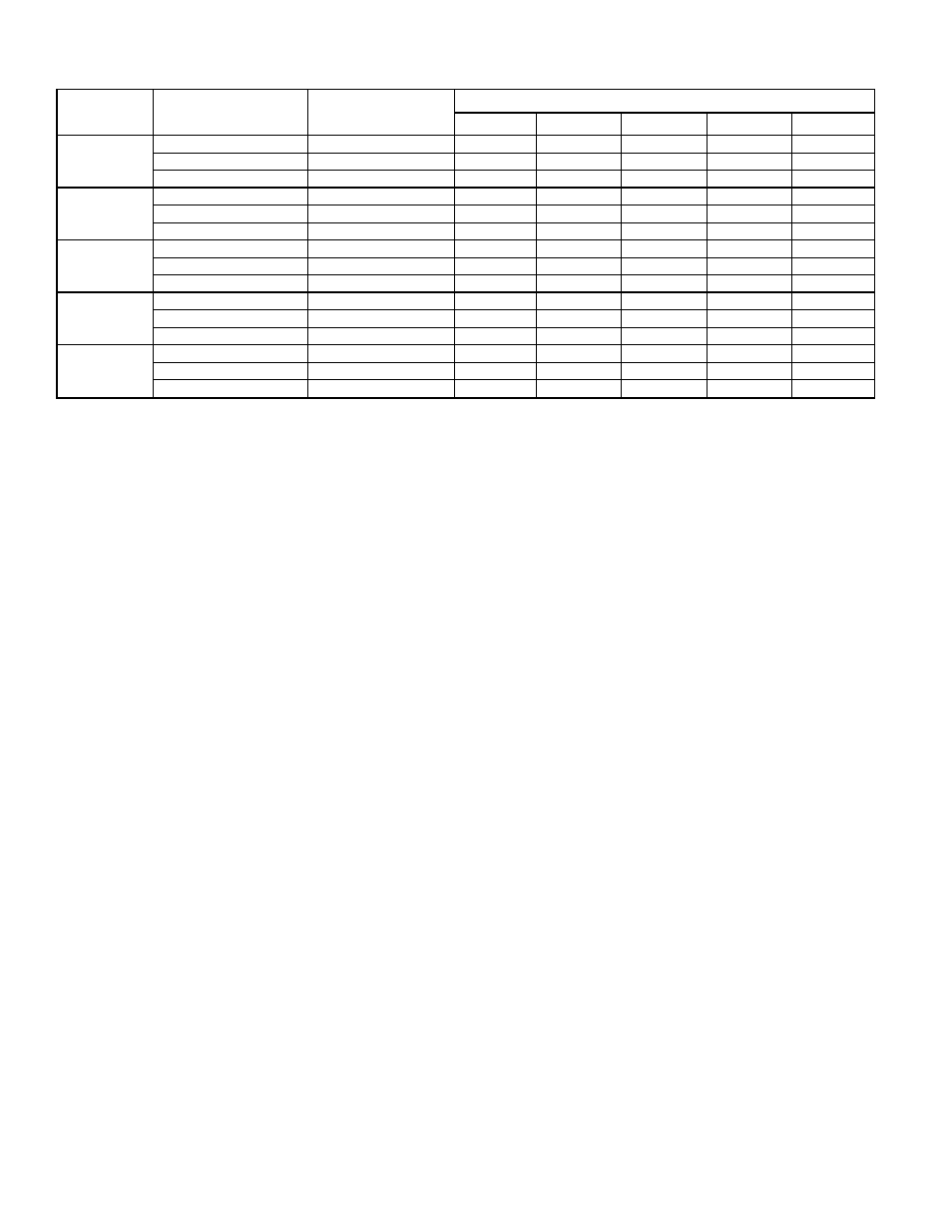
TABLE 7—MAXIMUM ALLOWABLE EXPOSED VENT PIPE LENGTH (FT) WITH INSULATION IN WINTER DESIGN
TEMPERATURE AMBIENT*
UNIT
SIZE
WINTER DESIGN
TEMPERATURE
(°F)
MAXIMUM PIPE
DIAMETER
(IN.)
INSULATION THICKNESS (IN.)†
0
3/8
1/2
3/4
1
042040
20
2
21
37
42
50
57
0
2
10
22
25
30
35
-20
2
5
14
17
21
25
042060
20
2
30
55
61
70
70
0
2
16
33
38
46
53
-20
2
9
23
26
33
38
042080
060080
20
2
37
65
70
70
70
0
2
20
39
45
55
63
-20
2
11
27
31
39
45
060100
20
2-1/2
41
70
70
70
70
0
2-1/2
21
42
48
59
68
-20
2-1/2
11
28
33
41
49
060120
20
3
49
70
70
70
70
0
3
26
51
58
70
70
-20
3
15
35
40
50
59
* Pipe length (ft) specified for maximum pipe lengths located in unconditioned spaces. Pipes located in unconditioned space cannot exceed total allowable pipe length as
specified in Table 6.
† Insulation thickness based on R value of 3.5 per in.
—28—