Bryant 355MAV EN User Manual
Page 18
NOTE:
Proper polarity must be maintained for 115-v wiring. If
polarity is incorrect, control center fault code indicator light will
flash rapidly and furnace will NOT operate.
WARNING:
The cabinet MUST have an uninterrupted
or unbroken ground according to NEC ANSI/NFPA
70-1996 and Canadian Electrical Code CSA C22.1 or
local codes to minimize personal injury if an electrical
fault should occur. This may consist of electrical wire or
conduit approved for electrical ground when installed in
accordance with existing electrical codes. Do not use gas
piping as an electrical ground. Failure to follow this
warning could result in electric shock, fire, or death.
J-BOX RELOCATION
1. Remove 2 screws holding auxiliary J-box. (See Fig. 23.)
2. Rotate J-box 180° and attach box to right side, using holes
provided.
CAUTION:
If manual disconnect switch is to be
mounted on furnace, select a location where a drill or
fastener will not contact electrical or gas components.
II.
24-V WIRING
Make field 24-v thermostat connections at 24-v terminal block on
control center. Y wire from thermostat MUST be connected to Y
terminal on control center, as shown in Fig. 22, for proper cooling
operation. The 24-v terminal board is marked for easy connection
of field wiring. (See Fig. 24.) The 24-v circuit contains a 3-amp,
automotive-type fuse located on control center. (See Fig. 25.) Any
electrical shorts of 24-v wiring during installation, service, or
maintenance may cause fuse to blow. If fuse replacement is
required, use only a fuse of identical size (3 amp).
→
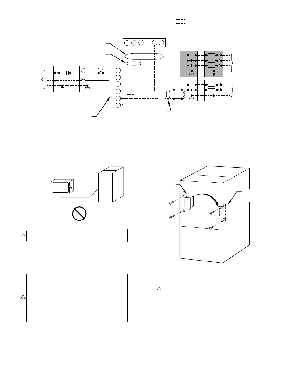
Fig. 22—Heating and Cooling Application Wiring Diagram
A96338
115-VOLT
FUSED
DISCONNECT
SWITCH
(WHEN REQUIRED)
115-VOLT
SINGLE
PHASE
AUXILIARY
J-BOX
FURNACE
CONTROL
CENTER
TWO WIRE
24-VOLT
TERMINAL
BLOCK
THREE-WIRE
HEATING
ONLY
FIVE
WIRE
NOTE 5
NOTE 1
NOTE
3
THERMOSTAT
TERMINALS
FIELD-SUPPLIED
FUSED DISCONNECT
CONDENSING
UNIT
R
W2
W
C
R
G
Y
GND
GND
GND
GND
FIELD 24-VOLT WIRING
FIELD 115-, 208/230-, 460-VOLT WIRING
FACTORY 24-VOLT WIRING
FACTORY 115-, 208/230-, 460-VOLT WIRING
208/230- OR
460-VOLT
THREE
PHASE
208/230-
VOLT
SINGLE
PHASE
W/W1
Y/Y2
G
C
NOTES:
1.
2.
3.
4.
5.
Connect Y or Y/Y2 terminal as shown for proper cooling operation.
Proper polarity must be maintained for 115-volt wiring.
Use W2 with 2-stage thermostat when zoning.
If any of the original wire, as supplied, must be replaced, use
same type or equivalent wire.
Some thermostats require a "C" terminal connection as shown.
CAUTION:
Do not connect aluminum wire between
disconnect switch and furnace. Use only copper wire.
A93033
COPPER
WIRE ONLY
ELECTRIC
DISCONNECT
SWITCH
ALUMINUM
WIRE
Fig. 23—Relocating J-Box
A93051
ALTERNATE
FIELD
LOCATION
FACTORY
INSTALLED
LOCATION
—18—
→