Bryant 310JAV User Manual
Page 5
CSA (A.G.A. and C.G.A.) listed gas conversion kit is required
to convert furnace for use with propane gas.
11. See Fig. 2 for required clearances to combustibles.
12. Maintain a 1-in. clearance from combustible materials to
supply air ductwork for a distance of 36 inches horizontally
from the furnace. See NFPA 90B or local code for further
requirements.
13. These furnaces SHALL NOT be installed directly on carpet-
ing, tile, or any other combustible material other than wood
flooring. In downflow installations, factory accessory floor
base MUST be used when installed on combustible materials
and wood flooring. Special base is not required when this
furnace is installed on manufacturer’s Coil Assembly Part No.
CD5 or CK5, or when Coil Box Part No. KCAKC is used.
INTRODUCTION
This 4–way multipoise Category I fan-assisted furnace is CSA
(A.G.A. and C.G.A.) design-certified for natural and propane gas
and for installation in alcoves, attics, basements, closets, utility
rooms, crawlspaces, and garages. A fan-assisted furnace is an
appliance equipped with an integral mechanical means to either
draw or force products of combustion through the combustion
chamber and/or heat exchanger. The furnace is factory-shipped for
use with natural gas. A CSA (A.G.A. and C.G.A.) listed gas
conversion kit is required to convert furnace for use with propane
gas. This furnace is not approved for installation in mobile homes,
recreational vehicles, or outdoors.
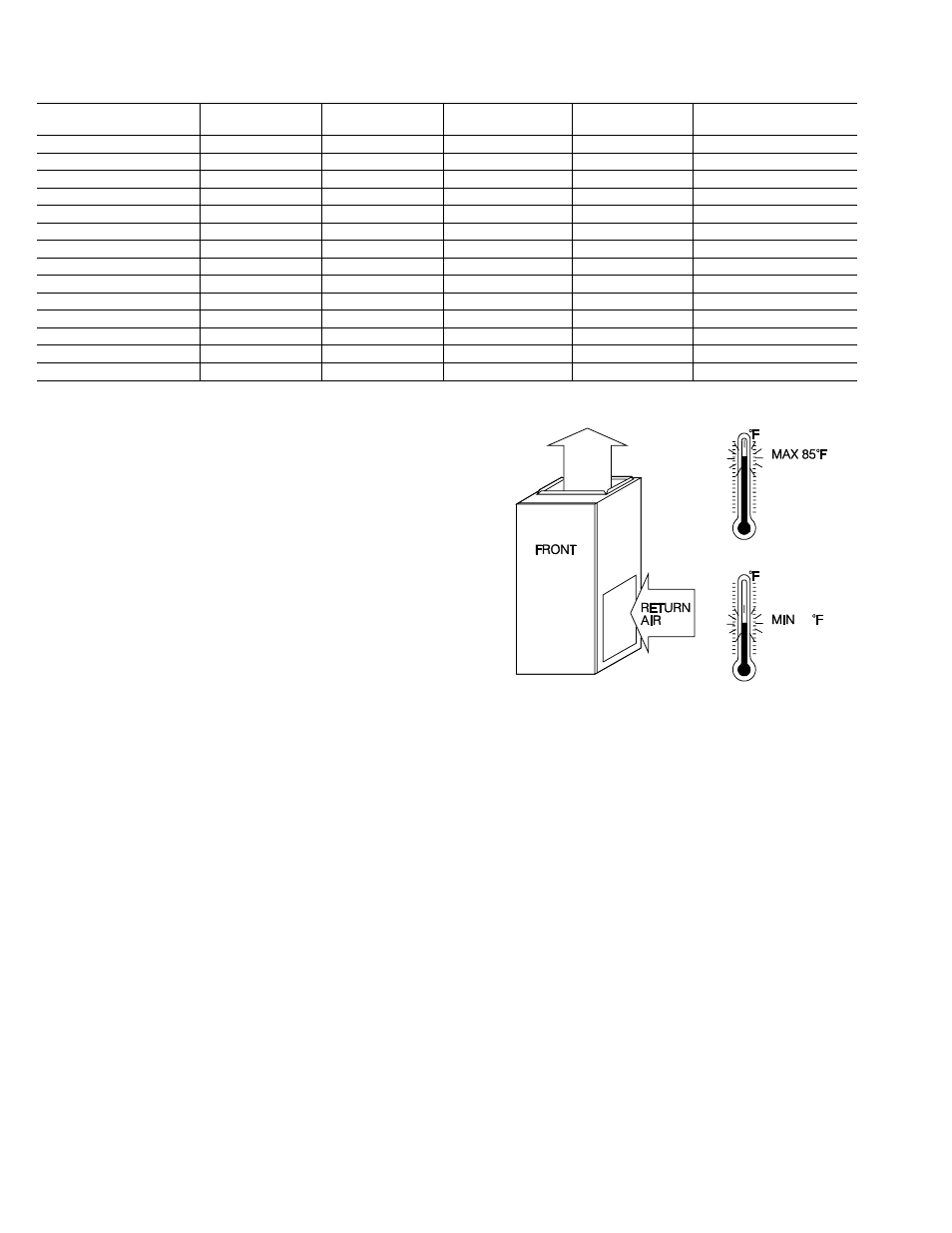
This furnace is designed for minimum continuous return-air
temperature of 60°F db or intermittent operation down to 55°F db
such as when used with a night setback thermostat. Return-air
temperature must not exceed 85°F db. Failure to follow these
return-air limits may affect reliability of heat exchangers, motors,
and controls. (See Fig. 3.)
For accessory installation details, refer to the applicable instruction
literature.
NOTE:
Remove all shipping brackets and materials before oper-
ating the furnace.
CODES AND STANDARDS
Follow all national and local codes and standards in addition to
these instructions. The installation must comply with regulations
of the serving gas supplier, local building, heating, plumbing, and
other codes. In absence of local codes, the installation must
comply with the national codes listed below and all authorities
having jurisdiction.
In the United States and Canada, follow all codes and standards for
the following:
Step 1—Safety
•
US: National Fuel Gas Code (NFGC) NFPA 54–2002/ANSI
Z223.1–2002 and the Installation Standards, Warm Air Heating
and Air Conditioning Systems ANSI/NFPA 90B
•
CANADA: CAN/CGA-B149.1–and .2–M00 National Standard
of Canada. Natural Gas and Propane Installation Codes (NSC-
NGPIC)
Step 2—General Installation
•
US: Current edition of the NFGC and the NFPA 90B. For
copies, contact the National Fire Protection Association Inc.,
Batterymarch Park, Quincy, MA 02269; or for only the NFGC,
contact the American Gas Association, 400 N. Capitol, N.W.,
Washington DC 20001 or www.NFPA.org.
•
CANADA: NSCNGPIC. For a copy, contact Standard Sales,
CSA International, 178 Rexdale Boulevard, Etobicoke (Tor-
onto), Ontario, M9W 1R3 Canada
Step 3—Combustion and Ventilation Air
•
US: Section 5.3 of the NFGC, Air for Combustion and
Ventilation
Table 1—Dimensions (IN.)
UNIT SIZE
A
B
C
VENT
CONN*
SHIP WT. (LB)
045-08/024045
14-3/16
12-9/16
12-11/16
4
104
045-12/036045
14-3/16
12-9/16
12-11/16
4
107
070-08/024070
14-3/16
12-9/16
12-11/16
4
111
070-12/036070
14-3/16
12-9/16
12-11/16
4
115
070-16/048070
17-1/2
15-7/8
16
4
123
090-14/042090
17-1/2
15-7/8
16
4
126
090-16/048090
21
19-3/8
19-1/2
4
139
090-20/060090
21
19-3/8
19-1/2
4
145
110-12/036110
17-1/2
15-7/8
16
4
134
110-16/048110
21
19-3/8
19-1/2
4
145
110-22/066110
21
19-3/8
19-1/2
4
151
135-16/048135
21
19-3/8
19-1/2
4
148
135-22/066135
24-1/2
22-7/8
23
4
163
155-20/060155
24-1/2
22-7/8
23
4
170
* 5” or 6” vent connector may be required in some cases.
Fig. 3—Return Air Temperature
A02055
60
4
→
→
→
→