Installation, Fig. 2—clearances to combustibles – Bryant 310JAV User Manual
Page 4
6. Always install furnace to operate within the furnace’s intended
temperature-rise range with a duct system which has an
external static pressure within the allowable range, as speci-
fied in the “Start-Up, Adjustments, and Safety Check” section.
See furnace rating plate.
7. When a furnace is installed so that supply ducts carry air
circulated by the furnace to areas outside the space containing
the furnace, the return air shall also be handled by duct(s)
sealed to the furnace casing and terminating outside the space
containing the furnace. See “Air Ducts” section.
8. A gas-fired furnace for installation in a residential garage must
be installed as specified in the warning box in the “Location”
section.
9. The furnace is not to be used for temporary heating of
buildings or structures under construction.
10. These Multipoise Gas-Fired Furnaces are CSA (A.G.A. and
C.G.A.) design-certified for natural and propane gases (see
furnace rating plate) and for installation in alcoves, attics,
basements, closets, utility rooms, crawlspaces, and garages.
The furnace is factory-shipped for use with natural gas. A
→
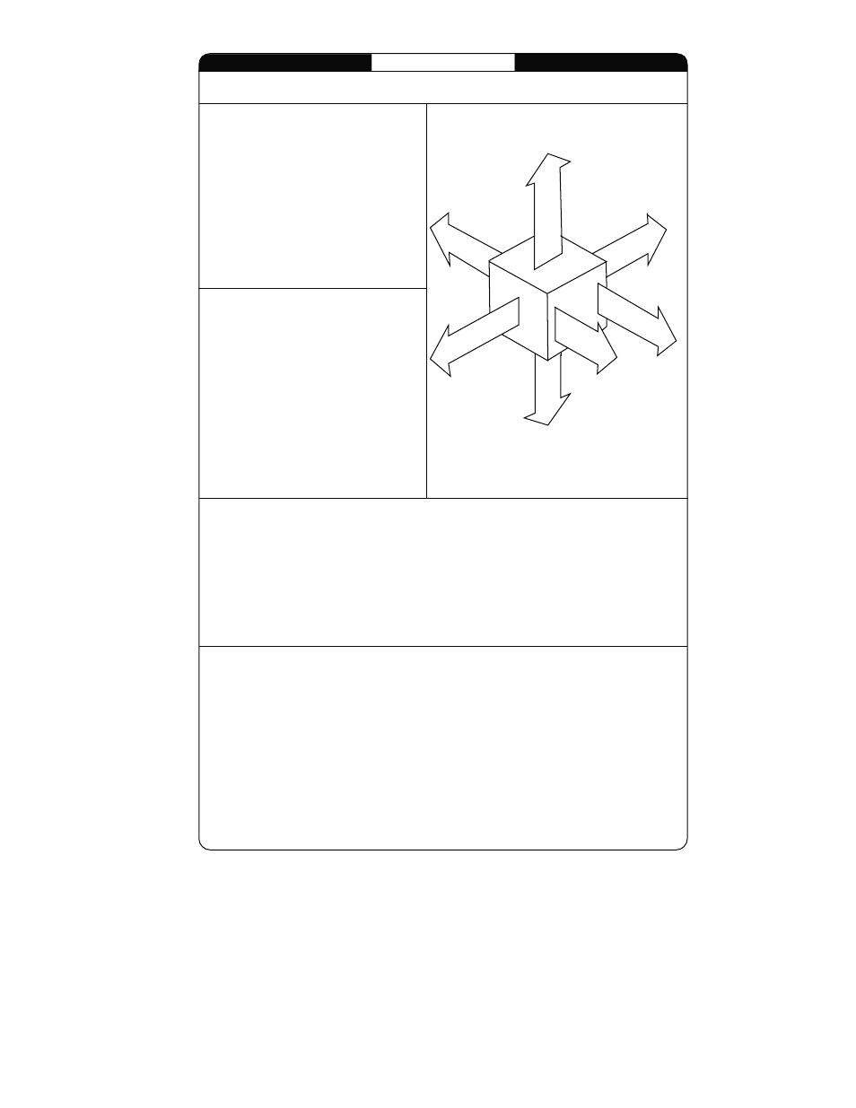
Fig. 2—Clearances to Combustibles
A02330
MINIMUM INCHES CLEARANCE TO COMBUSTIBLE CONSTRUCTION
Cette fournaise à air pulsé est équipée
pour utilisation avec
gaz naturel
et altitudes
comprises entre 0-3,050m (0-10,000 pi).
Utiliser une trousse de conversion, fournie par
le fabricant, pour passer au gaz propane ou pour
certaines installations au gaz naturel.
Cette fournaise est prévue pour être
installée dans un bâtiment construit sur place.
Cette fournaise peut être installée sur
un plancher combustible dans une alcôve ou
dans un garde-robe en respectant le minimum
d'espace libre des matériaux combustibles, tel
qu'indiqué sur le diagramme.
.
Cette fournaise peut être utilisée avec un
conduit d´évacuation de Type B-1 ou connectée
au conduit commun d´autres appareils à gaz.
.
DISTANCE MINIMALE EN POUCES AUX CONSTRUCTIONS COMBUSTIBLES
INSTALLATION
327590-101 REV. B
MINIMUM INCHES CLEARANCE TO COMBUSTIBLE CONSTRUCTION
DÉGAGEMENT MINIMUM EN POUCES AVEC ÉLÉMENTS
DE CONSTRUCTION COMBUSTIBLES
Ø
*
Installation on non-combustible floors only.
For Installation on combustible flooring only when installed on special base, Part No. KGASB0201ALL,
Coil Assembly, Part No. CD5 or CK5, or Coil Casing, Part No. KCAKC.
18 inches front clearance required for alcove.
Indicates supply or return sides when furnace is in the horizontal position. Line contact only permissible
between lines formed by intersections of the Top and two Sides of the furnace jacket, and building joists,
studs or framing.
Clearance in inches
Dégagement (po).
Clearance arrows
do not change with
furnace orientation.
Les fléches de dégagement
ne changent pas avec
l´orientation de la fournaise.
BO
T
T
O
M
D
E
SSO
U
S
0"
3"
0"
0"
1"
0"
30"
MIN
S I
D E
C
Ô T
É
F
R
O
N
T
A
V
A
N
T
B
C
K
A
R
R I
È
A
E
R
S
E
R V
I
E
C
EN
TR
T
E
N
E
I
V
A
N
A
T
F R
ON
T
S I
E
C
Ô T
È
F O
U
U
F
R N
A C S
E
E
I
A
R N
Ø
Vent Clearance to combustibles:
For Single Wall vents 6 inches (6 po).
For Type B-1 vent type 1 inch (1 po).
Dégagement de l´évent avec combustibles:
Pour conduit d´évacuation à paroi simple 6 po (6 inches).
Pour conduit d´évacuation de Type B-1 1 po (1 inch).
T
O
P /
PL
E
NUM
DE
SS
U
S
/ C
H
AMBRE
D
’AI
R
D
*
*
Cette fournaise est approuvée pour l´installation HORIZONTALE
et la circulation d´air VERS LE HAUT et VERS LE BAS.
†
†
This furnace is approved for UPFLOW, DOWNFLOW, and
HORIZONTAL installations.
MIN
Ø
*
†
Pour l´installation sur plancher non combustible seulement.
Pour l´installation sur un plancher combustible seulement quand on utilise la base spéciale, pièce
n KGASB0201ALL, l´ensemble serpentin, pièce n CD5 ou CK5, ou le carter de serpentin, pièce
n KCAKC.
Dans une alcôve, on doit maintenir un dégagement à l´avant de 18 po (450 mm).
La position indiquée concerne le côté d´entrée ou de retour quand la fournaise est dans la
position horizontale.
Le contact n´est permis qu´entre les lignes formées par les intersections du dessus et des
deux côtés de la chemise de la fournaise et les solives, montant sous cadre de charpente.
POUR LA POSITION COURANT DESCENDANT:
DOWNFLOW POSITIONS:
This forced air furnace is equipped for use with
natural gas at altitudes 0-10,000 ft (0-3,050m).
An accessory kit,
supplied by the
manufacturer,shall be used to convert to propane
gas use or may be required for some natural gas
applications.
This furnace is for indoor installation in a
building constructed on site.
This furnace may be installed on combustible
flooring in alcove or closet at minimum clearance
as indicated by the diagram from combustible
material .
This furnace may be used with a Type B-1 Vent
and may be vented in common with other gas-
fired appliances.
o
o
o
3
→