Bryant Air Handling Units 524J User Manual
Page 21
21
Centering Fan Wheel —
If fan and fan shaft assembly
are not properly centered, blades may scrape against the blower
side scroll plate or may create an objectionable whistling noise.
It may be necessary to adjust individual fan wheels or move en-
tire fan shaft. See the following two sections.
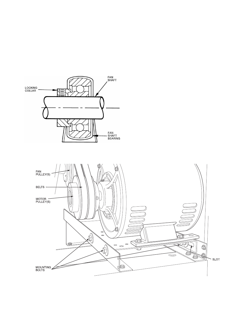
Fan Shaft Position Adjustment —
Loosen
setscrew or locking collar of each fan shaft bearing. Slide shaft
into correct position and replace locking collar (Fig. 20). To
replace locking collar, push collar up against inner face of
bearing. Turn collar in direction of fan rotation until tight, and
tighten setscrew. Tightening locking collar in direction of fan
rotation results in further tightening of collar should setscrew
work itself loose.
Fig. 20 — Fan Shaft Bearing
Individual Fan Wheel Adjustment —
Loosen the
2 locking bolts holding fan wheel hub to shaft. See Fig. 19.
Position fan wheel in center of the fan housing and tighten
locking bolts. Clearance between wheel and housing should be
the same on both sides.
Fan Belts —
Motor mounting plate and motor support
angles are slotted to permit both vertical and horizontal
adjustment. Adjust belt(s) for correct deflection by loosening
motor plate mounting bolts, moving motor/plate assembly
forward or back, and retightening bolts. Press down on belt
with one finger midway between fan and motor pulleys to
check deflection. For units with motor sizes up to and
including 3.7 Hp (2.76 kW), correct deflection is
3
/
16
-in.
(4.8 mm). For larger motor sizes, correct deflection is
1
/
8
-in.
(3.2 mm). See Fig.
21.
If complete belt replacement is required during servicing,
loosen the motor plate mounting bolts (Fig. 21), move motor/
plate assembly towards fan pulley, and pull belt(s) off pulleys.
Reverse the procedure with new bolts and readjust deflection.
Fan Rotation —
Correct fan rotation with respect to fan
outlet is shown in Fig. 22.
To reverse the direction of rotation of a 3-phase fan motor,
reverse any 2 of the power leads. Refer to the connection
diagram on the inside of motor terminal box cover for proper
reversing procedure of single-phase motor.
Fig. 21 — Fan Motor Mounting