P. 33), Edal settings, Control/expression)” (p. 33), will be in – Boss Audio Systems GT-100 User Manual
Page 33: Pedal settings (control/expression), Using pedals to control the parameters
33
Q
uick G
uide
O
ver
vie
w
O
utputting S
ound
Eff
ec
ts
Sa
ving
Pedal S
ettings
Sy
st
em
MIDI/USB
A
ppendix
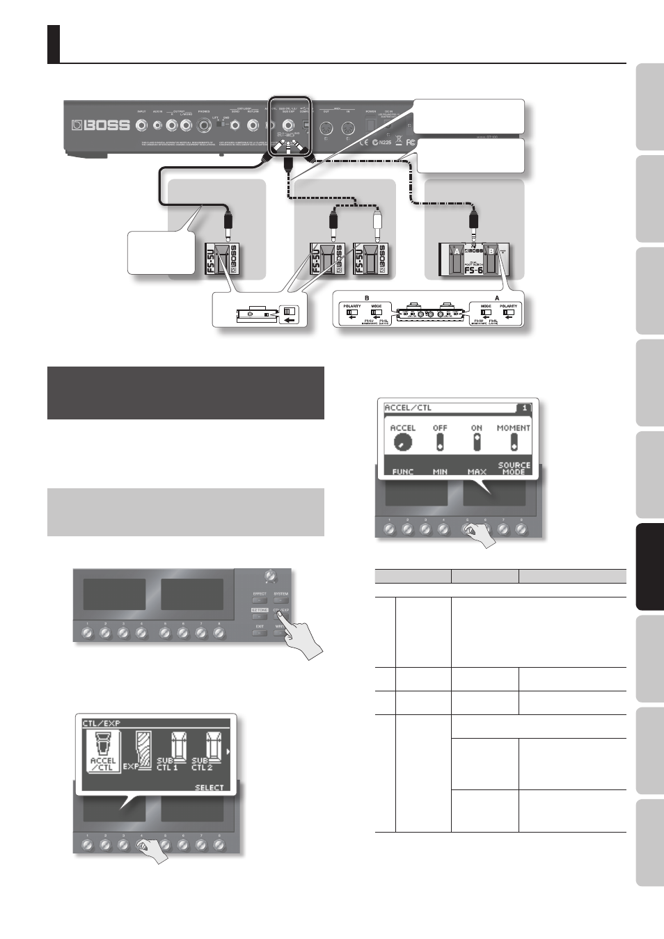
Pedal Settings (Control/Expression)
Using Pedals to Control the
Parameters
Here’s how to assign the parameters that will be controlled by the
ACCEL/CTL, EXP, SUB EXP, SUB CTL1, and SUB CTL2 pedals.
For details on each pedal, refer to “Front Panel” (p. 20) and ”Rear Panel
Assigning the ACCEL/CTL, EXP SW, SUB
CTL1, and SUB CTL2 Functions
1.
Press the [CTL/EXP] button .
2.
Turn knob [4] to select the pedal whose assignment you
want to specify .
3.
Use knob [5]–[8] to set the parameter that you want to
control .
Parameter
Value
Explanation
Page 1
[5]
FUNC
You can assign a variety of functions, such as
turning each effect on/off or switching the preamp
channel. For details on all parameters, download the
“GT-100 Parameter Guide” (PDF file) located under
“GT-100” in the list of “Owner’s Manuals” on the
Roland website (http://www.roland.com/support/
en/).
[6]
MIN
OFF, ON
(or STOP, START)
This sets the value for times
when the switch is Off.
[7]
MAX
OFF, ON
(or STOP, START)
This sets the value for times
when the switch is On.
[8]
SOURCE
MODE
This sets the behavior of the value each time the
switch is operation.
MOMENT
The normal state is Off
(minimum value), with the
switch On (maximum value)
only while the footswitch is
depressed.
TOGGLE
The setting is toggled On
(maximum value) or Off
(minimum value) with each
press of the footswitch.
* To be able to apply an Accel effect (p. 19) using the ACCEL/CTL
control pedal, you need to set ACCEL/CTL FUNC to ACCEL, and
set SOURCE MODE to MOMENT.
4.
Press the [EXIT] button to return to the Play screen .
Connect your foot switch to the SUB CTL 1, 2/SUB EXP jack as shown in the illustration, and set its POLARITY switch.
POLARITY switch
When Connecting an FS-5U
When Connecting Two FS-5Us
When Connecting an FS-6
Cable:
Stereo 1/4” phone type
1/4” phone type x 2
MODE/POLARITY switch
Cable:
1/4” phone type
fg
1/4” phone type
Cable:
Stereo 1/4” phone type fg
Stereo 1/4” phone type
or
or