9/14cbi, Fig. 33a. inner casing and control – Bosch 14/19CBI User Manual
Page 25
Fan -
Horizontal Flue. Remove the combustion
chamber cover. Carefully pull off the electrical connections and
the tubes from the air flow detector. Loosen the two clamps to
remove the fan . Refer to Fig 34.
Flue Hood - Horizontal Flue. Remove the fan, see
above. Remove the combustion chamber cover and withdraw
the hood. When refitting ensure that the combustion front fits
under the lip of the flue hood.
Burner Blade Assembly. Remove the combustion chamber
cover. Undo the screw at the right hand end of the burner.
Carefully pull-off the connections to the spark electrode. Slide the
burner blade assembly off the injector and remove. Carefully pull
off the flame sense electrode lead. Refer to Fig 33/33a.
Control Board Cover. To gain access to the control board remove
cover from the front clip, with a screwdriver (if necessary) and
unclip from the rear of the controls tray.
14.4 Component Cleaning
Do not use a brush with metal bristles to clean components.
Clean the fan taking care not to block air flow detector.
Clean the burner to ensure that the blades are clear. Do not use a
metal probe to clean the injector.
Clean the electrodes and check the alignment. Replace if there is
any sign of deterioration.
Clean the heat exchanger from top and bottom after covering the
burner injector. To clean the heat exchanger flueways remove the
stainless steel baffles from the appliance - the rear combustion
chamber cover can be tilted for better access. The front and rear
flueways can be cleaned with a brush being careful to protect the
rear combution chamber insulation. The inner flueway can be
cleaned with a scraper.
Check the combustion chamber insulation and replace if there is
any sign of damage or deterioration. Refer to Section 15.4.11.
Carefully refit any components removed and check that all
screws are tight and the connections properly re-made with the
appropriate gaskets/O-rings/seals.
Re-commission, as necessary, for correct operation to the users
requirements. Refer to Section 12 Commissioning.
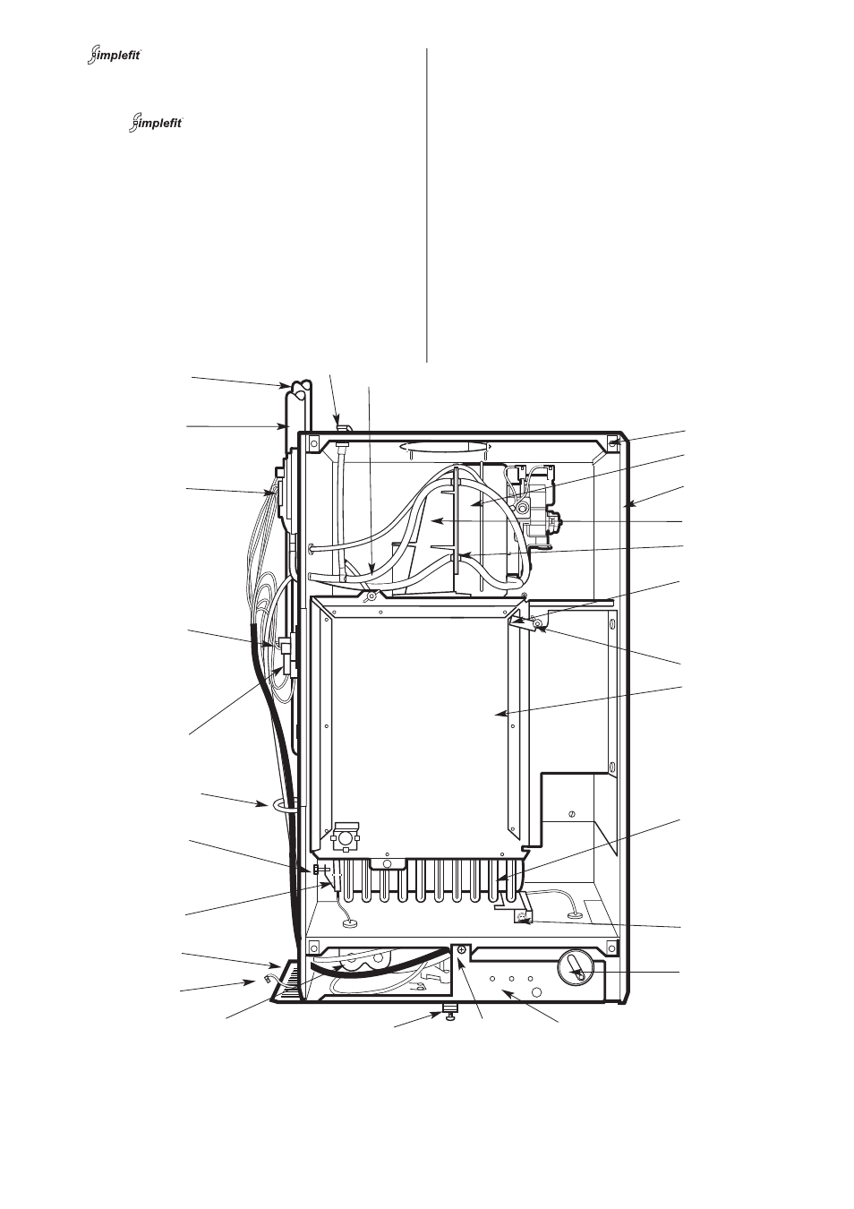
Fig. 33a. Inner Casing and control
9/14CBi
25
1. Inner case
8. Base/controls fixing screw
2. J bolts and wing nuts (2)
9. Cabinet fixing screw
3. Combustion chamber cover
10. Gas valve
4. Burner
11. Spark electrode
5. Burner fixing screw
12. Burner injector
6. Control knob
13. Temperature sensor
7. Indicator lights
14. Overheat thermostat
15. Air pressure switch
22. Inner case cover fixing points (4)
16. Flow pipe
23. Outer case earth tag
17. Return pipe
24. Side cover plate
18. Combustion test point
25. Wire clip
19. Sensing tubes
26. 9/14CBi clamping bracket
20. Fan
27. Pressure tube junction
21. Flue hood
1
2
22
3
4
5
6
7
8
9
10
11
12
13
14
15
16
17
18
19
21
20
23
24
26
25
27