Fig.20 . extension duct – Bosch 14/19CBI User Manual
Page 19
11.2.5 Flue Preparation
(i)
Drill the hole for the flue at Ø110mm unless the optional
internal fitting kit (WHS part No. 7 716 191 019) is used in
which case a Ø150mm hole is required.
(ii)
Fix the wall mounting plate onto the wall. Ensure it is level
before tightening the screws.
(iii)
The method of installation of the flue system may be
varied to suit the actual site conditions. The instructions
for connecting and fixing the ducts must, however, be
strictly followed.
Remove all packing material from the flue components.
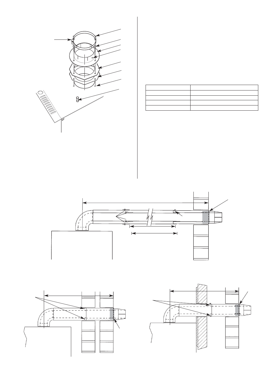
The standard telescopic flue assembly is suitable for lengths
from 425mm up to 725mm measured from the centre-line of the
boiler flue outlet to the outer face of the wall. Refer to Fig. 17.
If the length needed is greater than 725mm then extension duct
kit/s will be required - each kit extends the flue by 750mm up to
a maximum of 2.5m (19/24CBi) or 3.0m (9/14 and 14/19CBi).
See table below.
EXTENSION
MAXIMUM FLUE LENGTH mm
1
1475
2
2225
3
2500 (19/24CBi)
3
2975 (9/14 and 14/19CBi)
(iv)
Measure length L. Refer to Fig 20, 21, 22.
(v)
For installation of standard flue up to 750mm refer to
Section 11.2.6.
For installation of flue greater than 750mm refer to
Section 11.2.7.
For installation of bend kits refer to Sections above and
Section 11.2.8.
For installation of vertical adaptor refer to Section 11.2.9.
For installation of internal fitting kit refer to Sections
above and Section 11.2.10.
19
Fig.20 . Extension Duct.
L
Appliance casing
Fixing screws
Fixing screw
Turret
assembly
Terminal
assembly
Ducts of equal length
Shorten first extension fitted
to the turret assembly if more
than one extension is fitted
Fig.21. Flue duct length (side flue).
Fig.22 . Flue duct length (rear flue).
L
Flue
Turret
assembly
Terminal
assembly
Rear face of appliance
and face of mounting
wall
External
wall face
L
Fig.19. Flue turret fixing and combustion
sensing point
1
2
3
4
6
1. Flue spigot fixing screws
2. Flue spigot
3. Restrictor ring (if required)
4. Gasket
5. Flue spigot fixing holes
6. Combustion sensing
point
7. Clamping ring
8. Fixing screw hole
5
Tape
Fixing
screws
Tape
Fixing
screws
Tape
1
7
8