Bosch DHD Model User Manual
Page 11
11
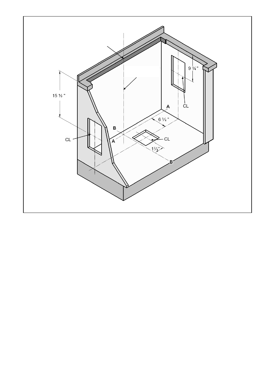
Fig. 8
Step 3: Prepare Duct Cutouts in
Cabinet
Y A. Refer to Figure 8. Drop a plumb-line
from Point ”P” at the rear center of the
countertop cutout. Mark this point on the
bottom of the cabinet below. Construct
two reference lines through this point:
one should be parallel to the cabinet
front and directly below the rear counter-
top cutout (Line A-A), and the other (Line
B-B) should be at right angles to A-A.
Y B. Using these reference lines as a base
for the measurements, layout the neces-
sary cabinet cutouts needed to imple-
ment the planned ductwork route. Where
a range of measurements is noted,
choose a measurement that allows best
clearance from wall studs, floor joists,
utilities, or other obstructions.
Step 3: Prepare Duct Cutouts in
Step 3: Cabinet
Y C. Before cutting for ducting, temporarily
set intake and cooktop in place and
attach integral blower (or duct transition
fitting if a remote or inline blower is instal-
led). Refer to steps 6 and 7. Verify that
the duct cutouts as marked will match
the hardware installation. Adjust the duct
cutout as necessary to match hardware
installation.
Y D. Remove temporarily placed hardware
and make cutouts in cabinet to accom-
modate ductwork installation.
Y E. Make all other cabinet modifications
needed to provide proper clearances for
drawers or removable shelving.
Note: Check boxes as tasks are completed.
Center Line (CL)/
Plumline
Point "P"