Bryant Single Package Rooftop Electric Heating/Electric Cooling Unit 558D User Manual
Page 14
Assembly
1. Determine if ventilation air is required in building. If
so, determine the minimum amount to be supplied by
each unit and record quantity of ventilation air needed
for use in Step 5.
2. Remove filter access panel by raising panel and swing-
ing panel outward. Panel is now disengaged from track
and can be removed. No tools are required to remove
filter access panel. Remove outdoor-air opening panel.
Save panels and screws. See Fig. 19.
3. Assemble outdoor-air hood top and side plates as shown
in Fig. 20. Install seal strips on hoop top and sides.
Put aside screen retainer and retainer screw for later
assembly. Do not attach hood to unit at this time.
4. Insert economizer plug into economizer harness. Re-
move tape from barometric relief damper. See Fig. 28.
5. If ventilation is not required, proceed to Step 6. If ven-
tilation air is required, perform the following:
a. Make sure the factory-installed jumper is in place
across terminals P and P1 on the economizer logic
module. T and T1 should be disconnected during
adjustment.
b. The 2 potentiometers with slots for adjustment are
located on the face of the economizer logic module.
Turn the lower potentiometer fully clockwise. The
dampers should be fully closed. Turn the potenti-
ometer gradually counterclockwise until the de-
sired position is reached.
c. Connect T and T1 to the 24V power supply.
ECONOMIZER
CONTROL
BOARD
BAROMETRIC
RELIEF
DAMPER
ECONOMIZER
PLUG
ECONOMIZER
MOTOR
Fig. 21 — Horizontal Durablade Economizer Installation
(90 Degree Rotation)
BLOCK-OFF PLATE
Fig. 22 — Horizontal Discharge Block-Off Plate
ECONOMIZER
CONTROL
BOARD
ECONOMIZER
PLUG
ECONOMIZER
MOTOR
TOP
SCREW
BAROMETRIC
RELIEF DAMPER
WIRING
HARNESS
POSITION SETTING
BRACKET
Fig. 23 — Durablade Economizer Installed in Unit
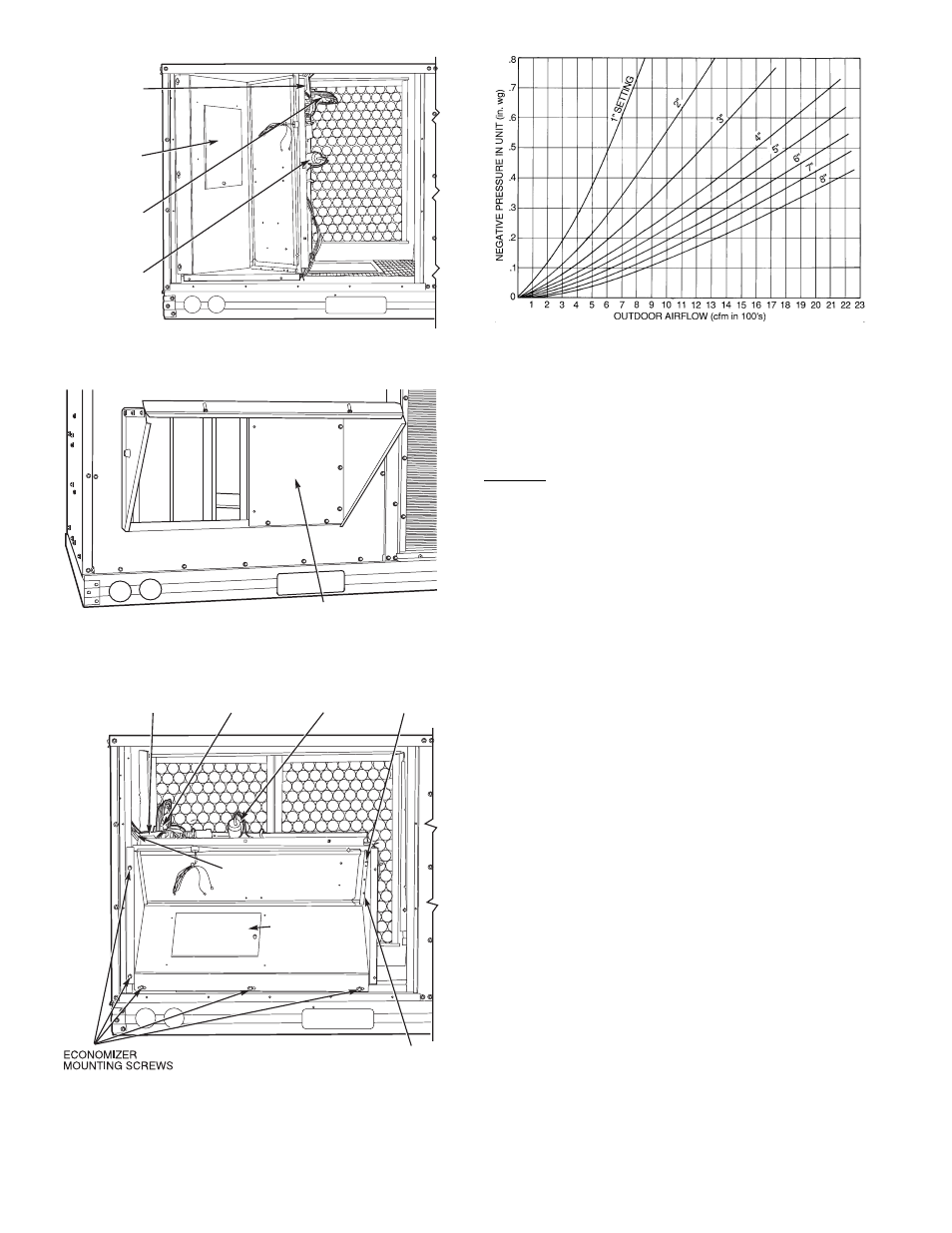
Example:
Given:
Negative Pressure . . . . . . . . . . . . . . . . . . . . . . . . . . . . 0.2 in. wg
Outdoor Air . . . . . . . . . . . . . . . . . . . . . . . . . . . . . . . . . . 900 cfm
Determine — Setting — 5 in.
Fig. 24 — Durablade Economizer Minimum Position Setting
—14—