Bryant Single Package Rooftop Electric Heating/Electric Cooling Unit 558D User Manual
Page 11
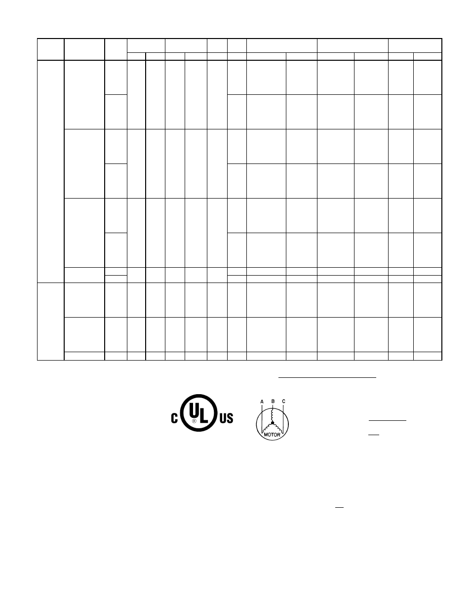
Table 2 — Electrical Data (Cont)
UNIT
558D
NOMINAL
V-PH-Hz
IFM
TYPE
VOLTAGE
RANGE
COMPR
(each)
OFM
IFM
ELECTRIC HEAT*
POWER SUPPLY
DISCONNECT
SIZE**
Min
Max
RLA
LRA
FLA
FLA
Nominal kW
FLA
MCA
MOCP†
FLA
LRA
060
(5 Ton)
208/230-1-60
Std
187
254
28.8
147
1.4
5.9
—
—
43.3/ 43.3
60/ 60
42/ 42
159/159
4.9/ 6.5
23.5/27.1
43.3/ 43.3
60/ 60
42/ 42
159/159
6.5/ 8.7
31.4/36.3
46.6/ 52.7
60/ 60
43/ 49
159/159
9.8/13.0
46.9/54.2
66.0/ 75.1
70/ 80††
61/ 69
159/159
13.0/17.4
62.8/72.5
85.9/ 98.0
90/100††
79/ 90
159/159
15.8/21.0
75.8/87.5
102.2/116.8
110/125††
94/107
159/159
Alt
8.8
—
—
46.2/ 46.2
60/ 60
45/ 45
162/162
4.9/ 6.5
23.5/27.1
46.2/ 46.2
60/ 60
45/ 45
162/162
6.5/ 8.7
31.4/36.3
49.9/ 55.9
60/ 60
46/ 52
162/162
9.8/13.0
46.9/54.2
69.3/ 78.3
70/ 80††
64/ 72
162/162
13.0/17.4
62.8/72.5
89.2/101.3
90/110††
82/ 93
162/162
15.8/21.0
75.8/87.5
105.5/120.0
110/125††
97/110
162/162
208/230-3-60
Std
187
254
16.3
114
1.4
5.9
—
—
27.7/ 27.7
35/ 35
27/ 27
126/126
4.9/ 6.5
13.6/15.6
27.7/ 27.7
35/ 35
27/ 27
126/126
7.9/10.5
21.9/25.3
34.7/ 38.9
40/ 40
32/ 36
126/126
12.0/16.0
33.4/38.5
49.1/ 55.5
50/ 60
46/ 51
126/126
15.8/21.0
43.8/50.5
62.1/ 70.5
70/ 80††
57/ 65
126/126
19.9/26.5
55.2/63.8
76.4/ 87.1
80/ 90††
70/ 80
126/126
Alt
5.8
—
—
26.8/ 26.8
40/ 40
27/ 27
125/125
4.9/ 6.5
13.6/15.6
26.8/ 26.8
40/ 40
27/ 27
125/125
7.9/10.5
21.9/25.3
35.3/ 39.5
45/ 45
32/ 36
125/125
12.0/16.0
33.4/38.5
49.6/ 56.0
60/ 60
45/ 51
125/125
15.8/21.0
43.8/50.5
62.6/ 71.1
70/ 80††
57/ 65
125/125
19.9/26.5
55.2/63.8
77.0/ 87.6
80/100††
70/ 80
125/125
460-3-60
Std
414
508
7.4
64
0.8
3.2
—
—
13.3
20
13
69
6.0
7.2
13.3
20
13
69
11.5
13.8
21.3
25
20
69
14.0
16.8
25.0
30
23
69
23.0
27.7
38.6
40
36
69
25.5
30.1
41.6
45
38
69
Alt
2.6
—
—
12.7
20
12
70
6.0
7.2
12.7
20
12
70
11.5
13.8
21.0
25
19
70
14.0
16.8
24.8
30
22
70
23.0
27.7
38.3
45
35
70
25.0
30.1
41.3
45
38
70
575-3-60
Std
518
632
6.2
52
0.8
3.2
—
—
11.8
15
12
57
Alt
2.6
—
—
11.2
15
12
59
072
(6 Ton)
208/230-3-60
Std
187
254
23.6
146.0
1.4
5.2
—
—
36.1/ 36.1
45/ 45
35/ 35
191/191
4.9/ 6.5
13.6/15.6
36.1/ 36.1
45/ 45
35/ 35
191/191
7.9/10.5
21.9/25.3
36.1/ 38.1
45/ 45
35/ 35
191/191
12.0/16.0
33.4/38.4
48.2/ 54.6
50/ 60
44/ 50
191/191
15.8/21.0
43.8/50.5
61.2/ 69.6
70/ 70††
56/ 64
191/191
19.9/26.5
55.2/63.8
75.6/ 86.2
80/ 90††
70/ 79
191/191
460-3-60
Std
414
508
10.6
73.0
0.8
2.6
—
—
16.7
20
16
90
6.0
7.2
16.7
20
16
90
11.5
13.8
20.5
25
19
90
14.0
16.8
24.3
25
22
90
23.0
27.8
37.8
40
35
90
25.5
30.7
41.6
45
38
90
575-3-60
Std
518
632
8.5
58.4
0.8
2.6
—
—
13.3
20
14
75
IMPORTANT: Optional, alternate evaporator-fan motor and drive are not available for
558D072 units. Contact your local representative for more information about field-
installed motors.
LEGEND
COMPR — Compressor
FLA
— Full Load Amps
HACR
— Heating, Air Conditioning and Refrigeration
IFM
— Indoor (Evaporator) Fan Motor
LRA
— Locked Rotor Amps
MCA
— Minimum Circuit Amps
MOCP
— Maximum Overcurrent Protection
NEC
— National Electrical Code
OFM
— Outdoor (Condenser) Fan Motor
RLA
— Rated Load Amps
*Available for field-installed accessory heaters only. Heater capacity (kW) is based on
heater voltage of 208 v, 240 v or 480 v. If power distribution voltage to unit varies from
rated heater voltage, heater kW will vary accordingly.
†Fuse or HACR circuit breaker.
**Used to determine minimum disconnect per NEC.
††Fusing single-point box provides the required branch circuit protection.
Ampacities are based on 460 v. MCA and MOCP are based on 575 v.
NOTES:
1. In compliance with NEC requirements for multimotor and combination load equip-
ment (refer to NEC Articles 430 and 440), the overcurrent protective device for the
unit shall be fuse or HACR breaker.
2. Unbalanced 3-Phase Supply Voltage
Never operate a motor where a phase imbalance in supply voltage is greater than
2%. Use the following formula to determine the percent of voltage imbalance.
% Voltage Imbalance
max voltage deviation from average voltage
= 100 x
average voltage
Example: Supply voltage is 460-3-60.
AB = 452 v
BC = 464 v
AC = 455 v
452 + 464 + 455
Average Voltage =
3
1371
=
3
=
457
NOTE: The 575-v units are Canada only.
Determine maximum deviation from average voltage.
(AB) 457 - 452 = 5 v
(BC) 464 - 457 = 7 v
(AC) 457 - 455 = 2 v
Maximum deviation is 7 v.
Determine percent voltage imbalance.
7
% Voltage Imbalance = 100 x
457
= 1.53%
This amount of phase imbalance is satisfactory as it is below the maximum allow-
able 2%.
IMPORTANT: If the supply voltage phase imbalance is more than 2%, contact your
local electric utility company immediately.
—11—