Agilent Technologies FS2010 User Manual
Page 10
10
The following explains how to connect the logic analyzer to the FS2010
for either state or timing analysis:
1. Connect the logic analyzer PODs 3 adapter cables, either the
E5378A or E5385A depending on the logic analyzer cards used.
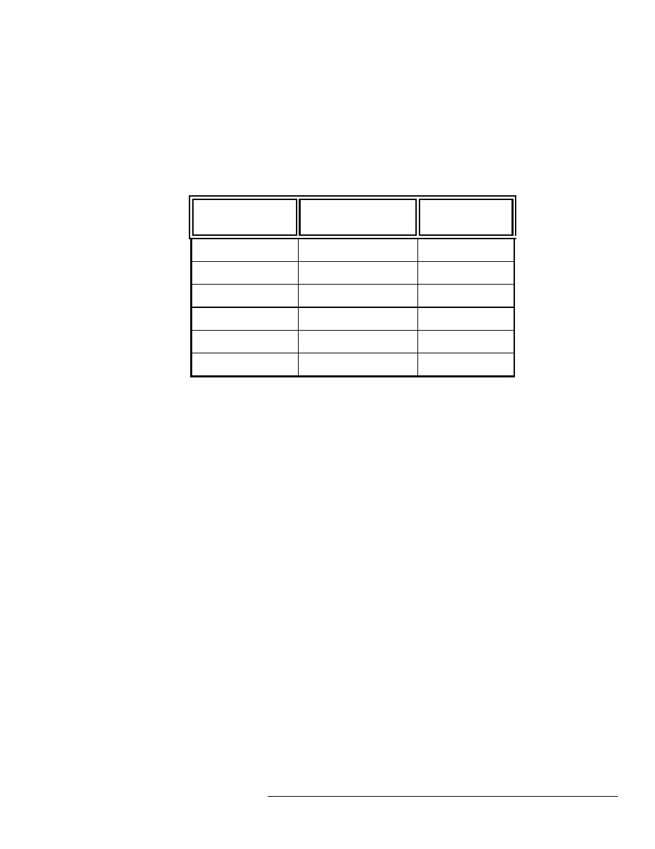
2. Plug the Adapter cables into the probe as shown in the table
below.
167XX/1655X
PCI-X Analysis Probe
connector
Comment
Master POD 1
J2 odd
J CLK
Master POD 2
J2 even
Master POD 3
J3 odd
Master POD 4
J3 even
Expander POD 1
J4 odd
optional 64 bit
Expander POD 2
J4 odd
optional 64 bit
The card edge connector of the FS2010 module can accommodate one
64 or 32 bit 3.3V PCI-X add-in card. To install simply align the module
with the connector and gently push the module in until it is seated in the
connector. There is sufficient clearance for the add-in card front plate.
The FS2010/PCI-X add-in card combination can then be installed in any
slot of the PCI-X Local bus.
When removing the PCI-X add-in card from the card edge extender
connector grasp the FS2010 with one hand and the PCI-X add-in card
with the other. Gently rock the PCI-X add-in card until it is free from the
connector.
The nature of an extender card is that it extends the etch length of the
bus. Due to the sensitivity of some PCI-X designs, extending the etch
length can interfere with the PCI-X add-in card operation. Operation of
the PCI-X add-in card when installed in the card edge extender
connector is not guaranteed.
Connecting the
167xx Agilent logic
analyzer to the
FS2010
How to install a PCI-X
add-in card into the
FS2010
System operation with
the PCI-X add-in card