Vollrath 238R User Manual
Page 19
11
3.3 OPERATING CONTROLS
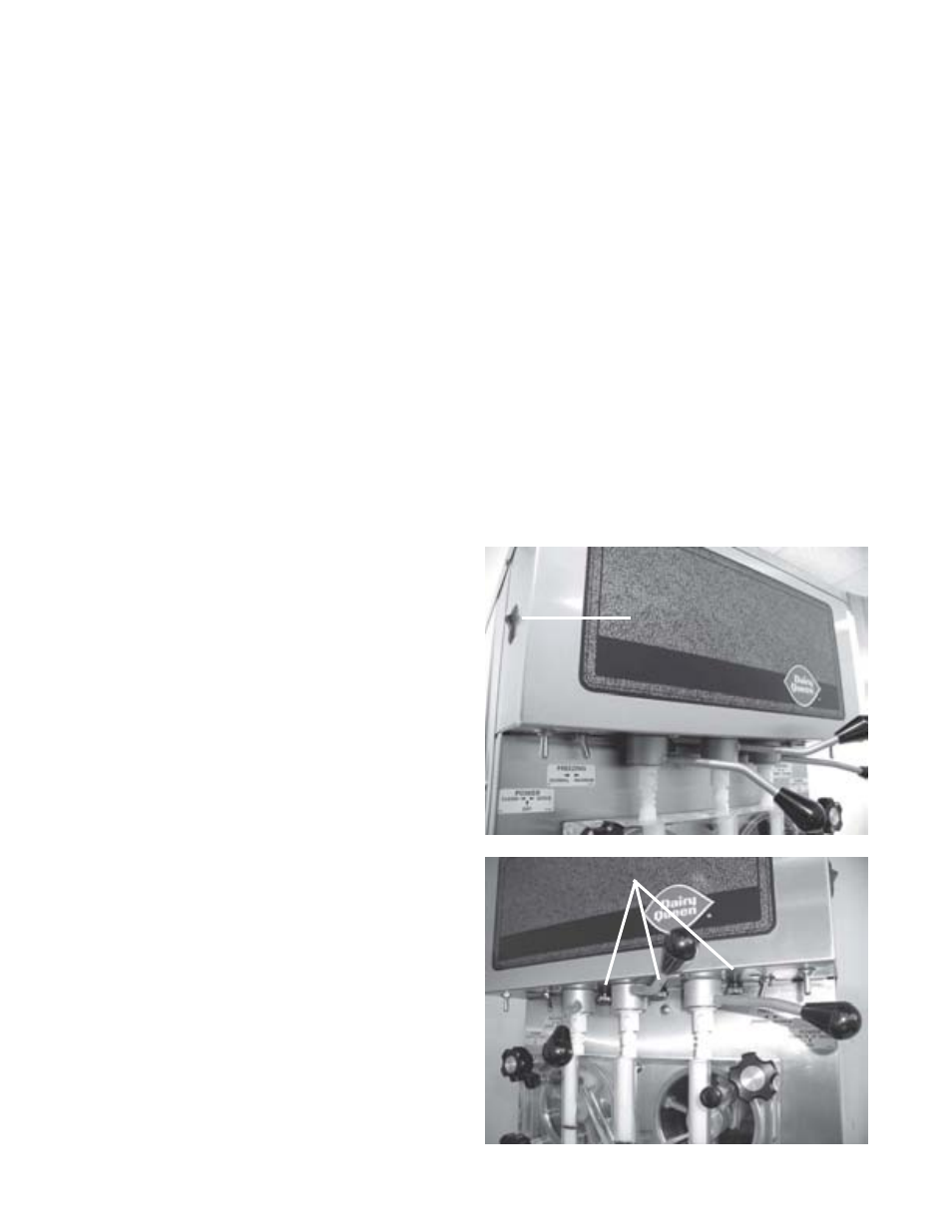
It is required that the operator know the function of each
control or component on the freezer before operating. Refer
to Fig.8 for the location of the operating controls.
3.4 SPIGOT SWITCH
The SPIGOT SWITCH will automatically activate the au-
ger drive and refrigeration system when the spigot switch
is opened to draw product.
3.5 DRIVE MOTOR OVERLOAD
The internal DRIVE MOTOR OVERLOAD will trip if the
drive motor is overloaded. It will reset after approximately
10-12 minutes. If the drive motor continues to trip, refer to
troubleshooting.
3.6 POWER SWITCH (Clean-Off-Serve)
The POWER switch is a three-position toggle switch used
to control the operation of the refrigeration system and
auger. When the switch is placed in the CLEAN position,
the refrigeration system will be off and the auger will ro-
tate for cleaning.
When the switch is placed in the OFF position, the refrig-
eration system and the auger are inoperative. When the
switch is placed in the SERVE position, the refrigeration
system and auger will be controlled automatically. The
switch must be placed in the SERVE position for normal
operation.
3.7 FREEZING SWITCH
The FREEZING switch is a two-position toggle switch used
to control the operation of the auger drive and refrigeration
system. When the switch is placed in the MAXIMUM po-
sition, the freezer will continue to run for a minimum of 30
seconds after the spigot is closed. This time cycle pro-
vides make-up cooling periods of heavy dispensing. Heavy
dispensing is drawing more than 18 ounces (.53 liters) in
one minute.
When the switch is placed in the NORMAL position, the
freezer will continue to run for a minimum of 5 seconds
after the spigot is closed. This time cycle is to be used
during periods of normal dispensing. Normal dispensing
is drawing less than 18 ounce (.53 liters) in one minute.
NOTE
Do not leave the switch in the MAXIMUM position
during slow or moderate dispensing as the product
temperature will become too cold.
3.8 DOOR INTERLOCK SWITCH
When the door is securely fastened the freezer will oper-
ate normally. When the door is removed the drive and
compressor will not run.
3.9 REMOTE PUMP SWITCH
The OFF-ON REMOTE PUMP SWITCH is a two-position
switch. When wired in series with the model 219 or U3
REMOTE PUMP OFF, pump operation can be controlled
from the front of the freezer. With the 219 or U3 REMOTE
PUMP OFF-ON SWITCH in the ON position, place the
OFF-ON pump switch in the ON position and the pump
will start. Place the OFF-ON switch in the OFF position
and the pump will stop.
3.10 DISPENSE RATE ADJUSTER
The dispense rate adjuster limits the opening of the spigot.
To adjust product dispense rate, turn the adjusting knob
clockwise for slower flow and counter-clockwise for faster
flow.
3.11 HIGH PRESSURE CUT OUT
If the head pressure exceeds 405 PSIG the high head
pressure cut out will trip. The reset button can be ac-
cessed from the lower front of the freezer.
3.12 SANITIZING PROCEDURES
For sanitizing to be effective, it must be performed after
the mix pump and freezer parts have been cleaned, and
just prior to filling the hopper or storage container with
mix. Sanitizing the night before is not effective.
When sanitizing the freezer, refer to local sanitary regula-
tions for applicable codes and recommended sanitizing
products and procedures. The frequency of sanitizing must
comply with local health regulations. Mix sanitizer ac-
cording to manufacturer’s instructions to provide a 100
parts per million strength solution. Mix sanitizer in quan-
tities of no less than 2 gallons (7.5 liters) of 120° F water
.
Allow sanitizer to contact the surfaces to be sanitized for
5 minutes. Any sanitizer must be used only in accordance
with the manufacturer’s instructions.
Figure 8. Operating Controls
Pump Switch
Dispenser Rate Adjusters