An364 – Cirrus Logic AN364 User Manual
Page 7
AN364
AN364REV3
7
Step 1) Select a Value for Boost Output Voltage
The value of the boost output voltage, V
BST
, must be greater than the maximum input AC line voltage peak.
The maximum V
BST
voltage, V
BST(max)
, should be kept as low as possible to help maintain the FET breakdown
requirement within economical constraints.
V
BST
is determined by an internal parameter and changes slightly depending on the type of dimmer detected.
With sense resistors R7, R8, R14, and R15 set to 1.5M
, the resulting V
BST
is approximately 405V for a 230V
system. For a 120V system, sense resistors R7, R8, R14, and R15 are set to 750k
each, and the resulting
V
BST
is approximately 200V. V
BST
is regulated by charging the boost output capacitor to its nominal value
each half line-cycle. V
BST
droops to its lowest value towards the end of each half line-cycle until the boosting
process starts again in the next half line-cycle.
Step 2) Select an Appropriate FET
Determine the FET breakdown voltage, V
Breakdown
, and reflected voltage, V
Reflected
. The FET maximum drain
voltage, V
Drain(max)
, is calculated using Equation 1.
The ringing associated with the transformer leakage inductance usually does not have enough energy to
cause a destructive avalanche breakdown. Voltages closely approaching the FET breakdown voltage are
acceptable.
Ideally, V
Reflected
should have nearly the same value as V
BST
because operating the transformer near 50%
duty cycle optimizes the transformer efficiency. Alternatively, V
CLAMP
should be much greater than V
Reflected
to rapidly discharge the energy stored in the transformer leakage inductance.
The FET breakdown voltage is constrained by cost and performance. A compromise must be reached in
partitioning voltage between V
BST
, V
CLAMP
, and V
Margin
. A second compromise will then determine how to
divide V
CLAMP
into V
Reflected
and a reasonable overshoot voltage portion, V
Overshoot
.
The losses caused by the leakage inductance are inversely proportional to V
Overshoot
, which is determined by
V
Drain max
V
BST max
V
CLAMP max
+
=
[Eq. 1]
V
Overshoot
V
CLAMP
V
Reflecteed
–
=
[Eq. 2]
Overshoot is a brief condition
above V
Reflected
, required to
quickly dissipate the energy stored
in the transformer leakage
inductance.
During this time, the primary
current is kept from transferring to
the secondary, siphoning energy
from the load to the clamp zener
(snubber).
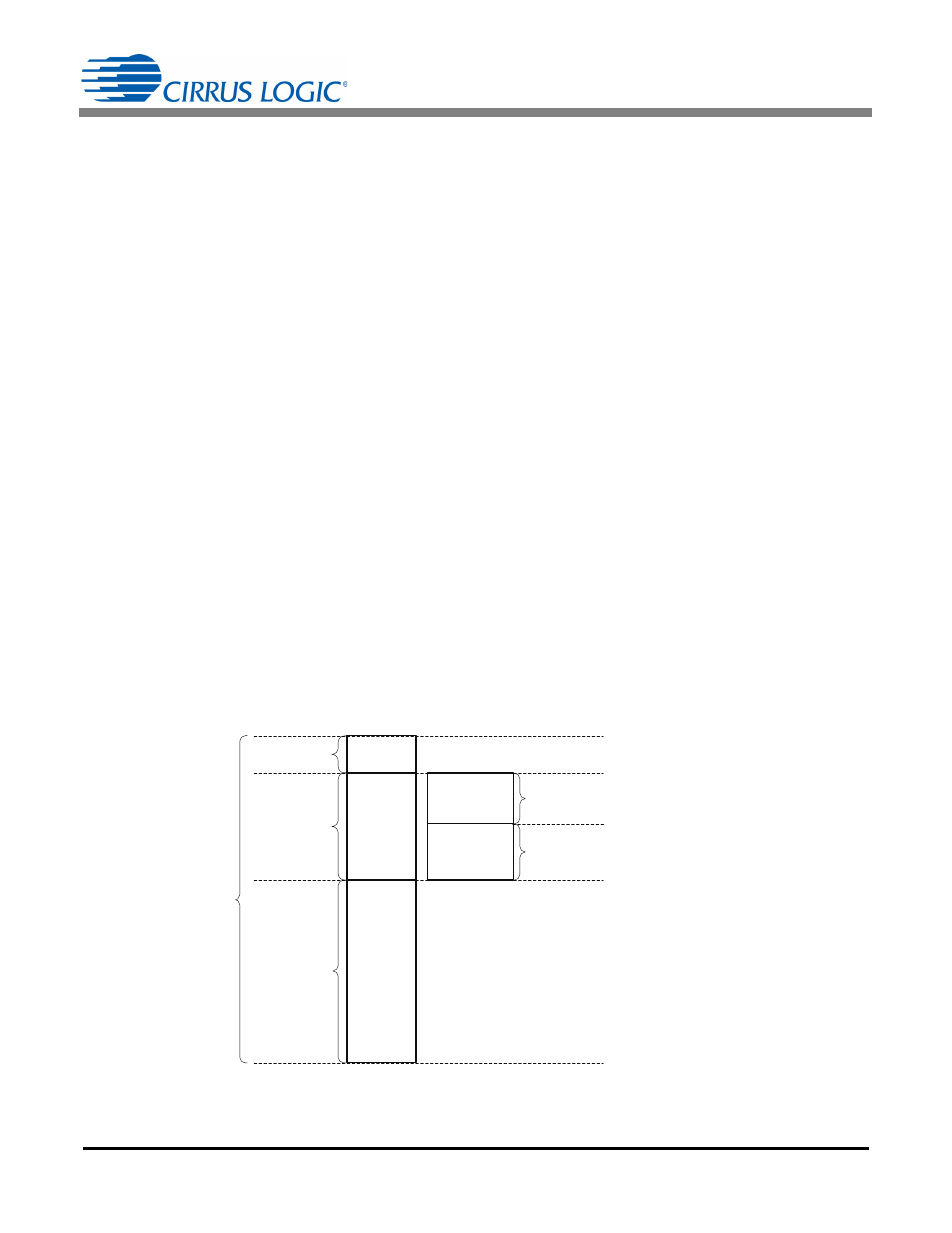
Figure 3. FET Breakdown Voltage
V
Margin
V
CLAMP
V
BST
V
Overshoot
V
Reflected
FET Breakdown
Voltage Rating
Clamp
Voltage
Boost Output
Voltage
Margin
Reflected
Voltage
Overshoot
Voltage