Tive divider as illustrated in figure 3 – Cirrus Logic CS5526 User Manual
Page 9
CS5525 CS5526
DS202F5
9
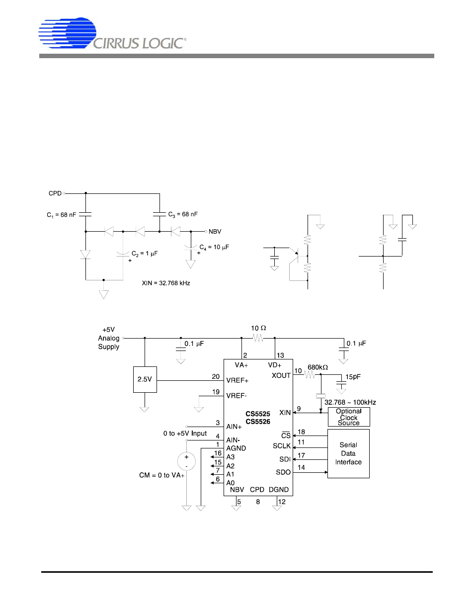
Figure 4 illustrates the CS5525/26 connected to
measure ground referenced unipolar signals of a
positive polarity using the 1 V, 2.5 V, and 5 V input
voltage ranges on the converter. For the 25 mV, 55
mV, and 100 mV ranges the signal must have a
common mode near +2.5 V (NBV = 0V).
The CS5525/26 are optimized for the measurement
of thermocouple outputs, but they are also well
suited for the measurement of ratiometric bridge
transducer outputs. Figure 5 illustrates the
CS5525/26 connected to measure the output of a
ratiometric differential bridge transducer while op-
erating from a single +5 V supply.
-5 V
N B V
3 0 .1 K
3 4 .8 K
2 N 5 0 8 7
o r s im ila r
-5 V
2 .1 K
2 .0 K
N B V
+
1 0
µF
1 0
µF
+
Figure 2. Charge Pump Drive Circuit for VD+ = 3 V.
Figure 3. Alternate NBV Circuits.
Figure 4. CS5525/26 Configured for ground-referenced Unipolar Signals.