Configuration register – Cirrus Logic CS5526 User Manual
Page 12
CS5525 CS5526
12
DS202F5
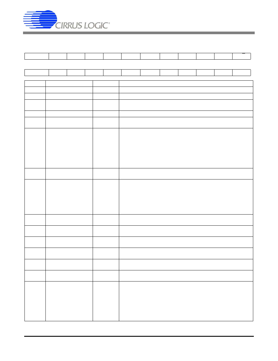
Configuration Register
* R indicates the bit value after the part is reset
D23(MSB)
D22
D21
D20
D19
D18
D17
D16
D15
D14
D13
D12
A3
A2
A1
A0
NU
CFS
NU
LPM
WR2
WR1
WR0
U/B
D11
D10
D9
D8
D7
D6
D5
D4
D3
D2
D1
D0
G2
G1
G0
PD
RS
RV
PF
PSS
DF
CC2
CC1
CC0
BIT
NAME
VALUE
FUNCTION
D23-D20
Latch Outputs, A3-A0
0000
R* Latch Output Pins A3-A0 mimic the D23-D20 Register bits.
D19
Not Used, NU
0
R Must always be logic 0.
D18
Chop Frequency Select,
CFS
0
1
R 256 Hz Amplifier chop frequency
32768 Hz Amplifier chop frequency
D17
Not Used, NU
0
R Must always be logic 0.
D16
Low Power Mode, LPM
0
1
R Normal Mode
Reduced Power mode
D15-D13
Word Rate, WR2-0
Note: For
XIN = 32.768kHz
000
001
010
011
100
101
110
111
R 15.0 Sps (2182 XIN cycles)
30.1 Sps (1090 XIN cycles)
60.0 Sps (546 XIN cycles)
123.2 Sps (266 XIN cycles)
168.9 Sps (194 XIN cycles)
202.3 Sps (162 XIN cycles)
3.76 Sps (8722 XIN cycles)
7.51 Sps (4362 XIN cycles)
D12
Unipolar/Bipolar, U/B
0
1
R Bipolar Measurement mode
Unipolar Measurement mode
D11-D9
Gain Bits, G2-G0
000
001
010
011
100
101
110/111
R 100 mV (assumes VREF = 2.5V)
55 mV
25 mV
1 V
5.0 V
2.5 V
Not Used.
D8
Pump Disable, PD
0
1
R Charge Pump Enabled
For PD = 1, the CPD pin goes to a Hi-Z output state.
D7
Reset System, RS
0
1
R Normal Operation
Activate a Reset cycle. To return to Normal Operation write bit to zero.
D6
Reset Valid , RV
0
1
R
No reset has occurred or bit has been cleared (read only).
Valid Reset has occurred. (Cleared when read.)
D5
Port Flag, PF
0
1
R Port Flag mode inactive
Port Flag mode active
D4
Power Save Select, PSS
0
1
R Standby Mode (Oscillator active, allows quick power-up)
Sleep Mode (Oscillator inactive)
D3
Done Flag, DF
0
1
R Done Flag bit is cleared (read only).
Calibration or Conversion cycle completed (read only).
D2-D0
Calibration Control Bits,
CC2-CC0
000
001
010
011
100
101
110
111
R Normal Operation (no calibration)
Offset -- Self-Calibration
Gain -- Self-Calibration
Offset Self-Calibration followed by Gain Self-Calibration
Not used.
Offset -- System Calibration
Gain -- System Calibration
Not Used.
Table 2. Configuration Register