Recommended operating conditions, Absolute maximum ratings – Cirrus Logic CS5508 User Manual
Page 12
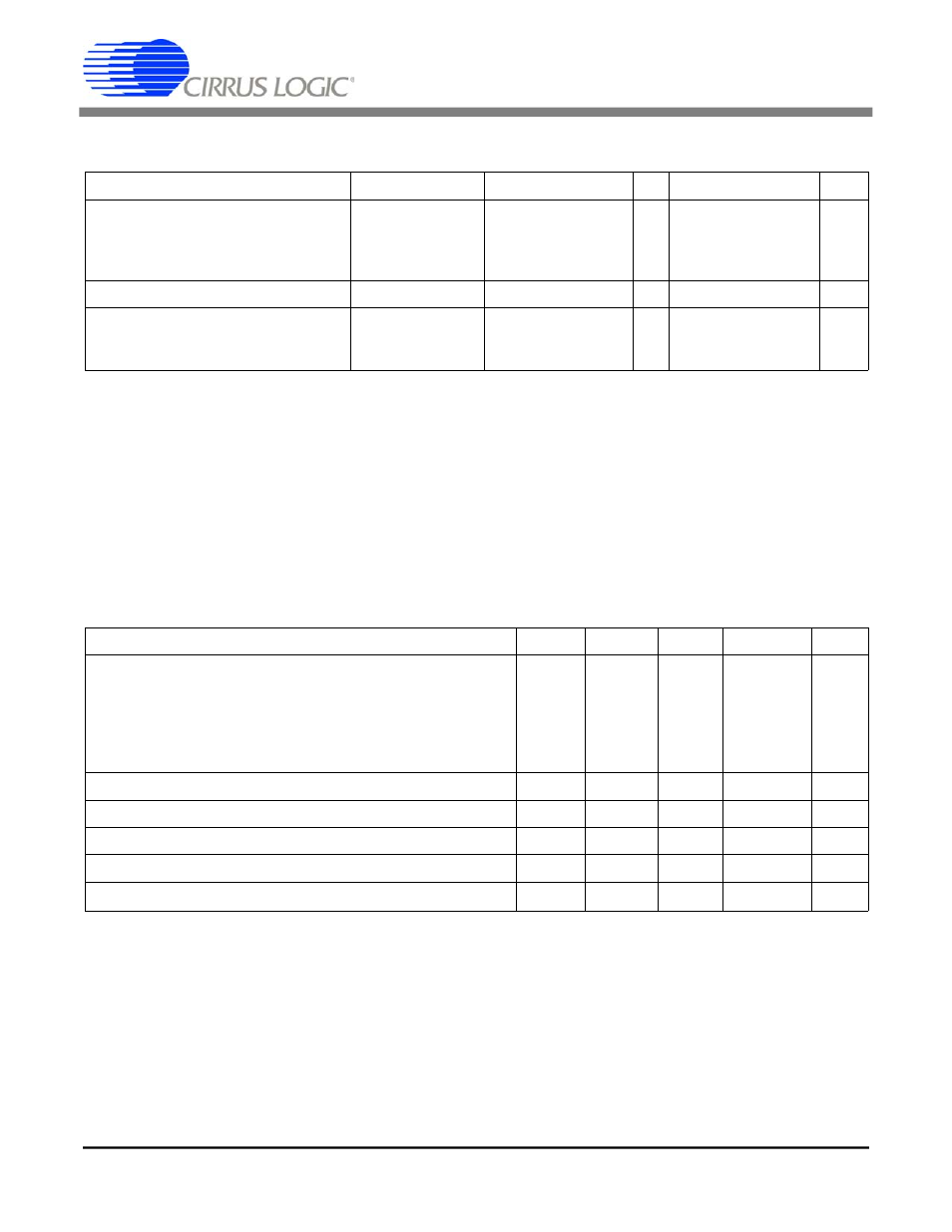
RECOMMENDED OPERATING CONDITIONS
(DGND = 0V) (Note 19)
Parameter
Symbol
Min
Typ
Max
Units
DC Power Supplies: Positive Digital
(VA+)-(VA-)
Positive Analog
Negative Analog
VD+
V
diff
VA+
VA-
3.15
4.75
4.5
0
5.0
10
5.0
-5.0
5.5
11
11
-5.5
V
V
V
V
Analog Reference Voltage (Note 20) (VREF+)-(VREF-)
1.0
2.5
3.6
V
Analog Input Voltage:
(Note 21)
Unipolar
Bipolar
VAIN
VAIN
0
-((VREF+)-(VREF-))
-
-
(VREF+)-(VREF-)
+((VREF+)-(VREF-))
V
V
Notes: 19. All voltages with respect to ground.
20. The CS5505/6/7/8 can be operated with a reference voltage as low as 100 mV; but with a
corresponding reduction in nois e-free resolution. The common mode voltage of the voltage reference
may be any value as long as +V REF and -VREF remain inside the supply values of VA+ and VA-.
21. The CS5505/6/7/8 can acc ept input voltages up to the analog suppl ies (VA+ and VA-). In unipolar
mode the CS5505/6/7/8 wil l output all 1’s if the dc input magnitude ( (AIN+)-(AIN-)) exceeds
((VREF+)-(VREF-)) and will output all 0’s if the input becomes more negative than 0 Volts.
In bipolar mode the CS5505/6/7/8 will output all 1’s if the dc input magnitude ((AIN+)-(AIN-)) exceeds
((VREF+)-(VREF-)) and will output all 0’s if the input becomes more negative in magnitude than
-((VREF+)-(VREF-)).
ABSOLUTE MAXIMUM RATINGS*
Parameter
Symbol
Min
Typ
Max
Units
DC Power Supplies:
Digital Ground
(Note 22)
Positive Digital
(Note 23)
Positive Analog
Negative Analog
(VA+)-(VA-)
(VA+)-(VD+)
DGND
VD+
VA+
VA-
V
diff1
V
diff2
-0.3
-0.3
-0.3
+0.3
-0.3
-0.3
-
-
-
-
-
-
(VD+)-0.3
6.0 or VA+
12.0
-6.0
12.0
12.0
V
V
V
V
V
V
Input Current, Any Pin Except Supplies
(Notes 24, 25)
I
in
-
-
±10
mA
Analog Input Voltage
AIN and VREF pins
V
INA
(VA-)-0.3
-
(VA+)+0.3
V
Digital Input Voltage
V
IND
-0.3
-
(VD+)+0.3
V
Ambient Operating Temperature
T
A
-55
-
125
°C
Storage Temperature
T
stg
-65
-
150
°C
Notes: 22. No pin should go more positive than (VA+)+0.3V.
23. VD+ must always be less than (VA+)+0.3 V,and can never exceed 6.0V.
24. Applies to all pins including continuous overvoltage conditions at the analog input (AIN) pin.
25. Transient currents of up to 100mA will not cause SCR latch-up. Maximum input current for a power
supply pin is
± 50 mA.
* WARNING: Operation at or beyond these limits may result in permanent damage to the device.
Normal operation is not guaranteed at these extremes.
CS5505/6/7/8
12
DS59F4
CS5505/6/7/8
12
DS59F7