Bridge transducer digitizer circuits, 6an31rev3 – Cirrus Logic AN31 User Manual
Page 6
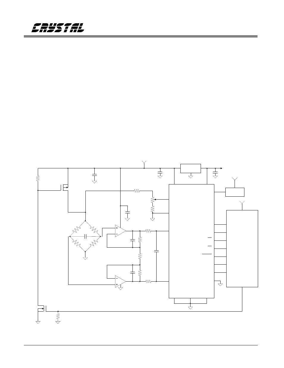
Figure 5 illustrates an application which uses an
instrumentation amplifier to amplify and convert
the differential bridge signal to a
ground-referenced signal for the converter. Full
scale for the converter is set by the divider
resistors which determine the voltage reference
input to the VREF+/- pins of the converter. The
reference voltage in the figure is set to 2.5 V.
The bridge sensitivity is 2 mV/V so the full
scale bridge output is 20 mV. This is amplified
by the 100 gain of the instrumentation amplifier
to obtain 2.0 V into the converter. The converter
can be operated in either unipolar or bipolar
mode. Up to four load cells, each with its own
amplifier, can be input to the CS5506. The
measurement assumes the voltage reference will
remain ratiometric across all four load cells.
CS5507 Switched-Bridge Low-power
Digitizer with +10 V Excitation
Some applications call for reduced operating
power. One method of significantly reducing the
power consumption is to apply the supply
voltage to the bridge transducer only when a
18.7k
0.015
0.015
18.7k
VA+
VREF+
VREF-
AIN+
CS5507
16 bits
AIN-
VREFOUT
VA-
DGND
SCLK
SDATA
CONV
CAL
5k
10k
350
350
350
350
3
2
1
6
5
4
7
LT1013
BP/UP
-
14
3
2
1
7
20
19
18
4
11
CS
DRDY
16
13
10
15
8
12
0.1
8
x166
10
100k
TP0610L
100k
2N7000
100pF
0.047
System
Microcontroller
+5
100
100
XIN
+5V Regulator
162 kHz
OSC
VD+
17
0.1
+
2 mV/V
Transducer
0.1
+5
+
+10
Q2
Q1
M/SLP
6
226
Optional
Gain
Trim
500
+5
≈
3.33 V
1 Conversion = 20 msec
Q1, Q2 Siliconix
Figure 6. CS5507 Switched-Bridge Low-power Digitizer with +10 Volt Excitation.
Bridge Transducer Digitizer Circuits
6
AN31REV3