Bridge transducer digitizer circuits – Cirrus Logic AN31 User Manual
Page 16
the converter is flipped and a conversion is
performed on channel one of the converter. The
negative answer for channel one is then
subtracted from the previous positive reading
from channel one.
The resultant readings from each channel can be
averaged to reduce the effects of noise. Then the
readings from the two channels are ratioed. The
channel two data represents the value of the
excitation on the bridge. Channel one data
represents the output signal from the bridge as a
proportion of the bridge voltage. By ratioing the
data (AIN1/AIN2) any drift in the bridge
excitation voltage (such as those caused by
changes in the driver output impedance) is
compensated.
The circuit can read both channels and calculate
a final answer for the bridge signal in less than
25 msec.; which means an output word can be
calculated at a rate of 40 times per second. If 20
output words are averaged the circuit will yield
better than 100,000 noise-free counts with the
offset drift of the digitizer being less than 50 nV
over time.
VA+
VD+
VREF+
VREF-
AIN1+
CS5504
20 bits
AIN1-
A0
VA-
DGND
SCLK
SDATA
CONV
CAL
XIN
3
2
6
2
3
4
6
LT1007
4
3
2
20
14
17
CS
DRDY
1
16
10
15
8
7
2k
2k
1k
2mV/V
Transducer
+5
4
100
0.005
100
7
+5
+5
-5
10k
10k
2k
3
4
5
6
2
7
0.1
10
+
MIC4428
+5
3.83k
10k
≈
3.6V
0.1
0.1
10
AIN2+
AIN2-
-5
0.1
19
18
330 kHz
OSC
11
9
13
12
7
5
350
+
-
350
350
350
100pF
System
Microcontroller
49.9k
49.9k
+5
Optional
Gain
Trim
1k
500
0.005
0.005
604
10k
2N3906
≈
3.33V
0.01
0.01
-5
-5
-5
BP/UP
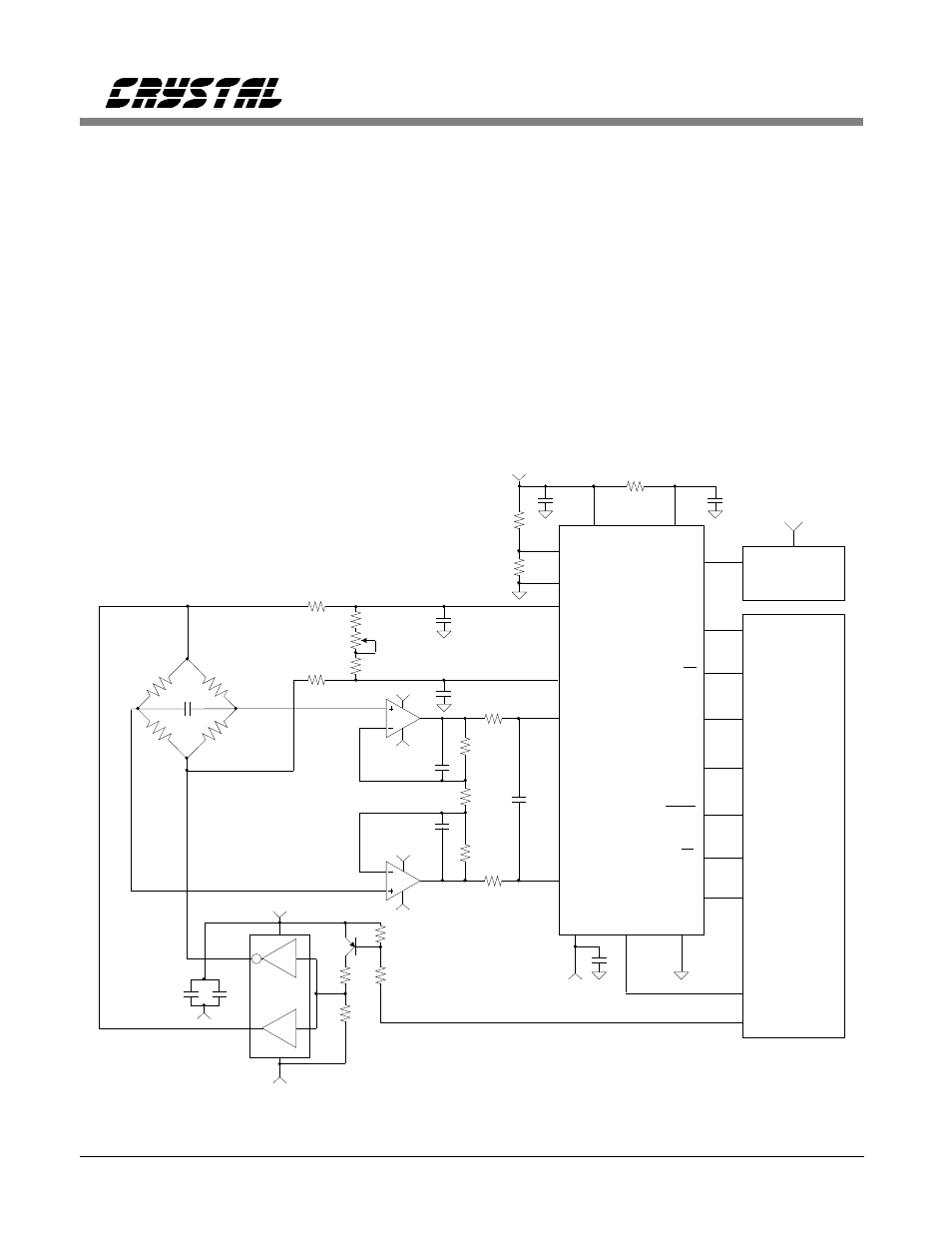
40 Conversions/sec
before averaging
Figure 12. Switched Bridge with CS5504 Using
±
5 Volt Analog Supplies.
Bridge Transducer Digitizer Circuits
16
AN31REV3