Cs5516 – Cirrus Logic AN31 User Manual
Page 20
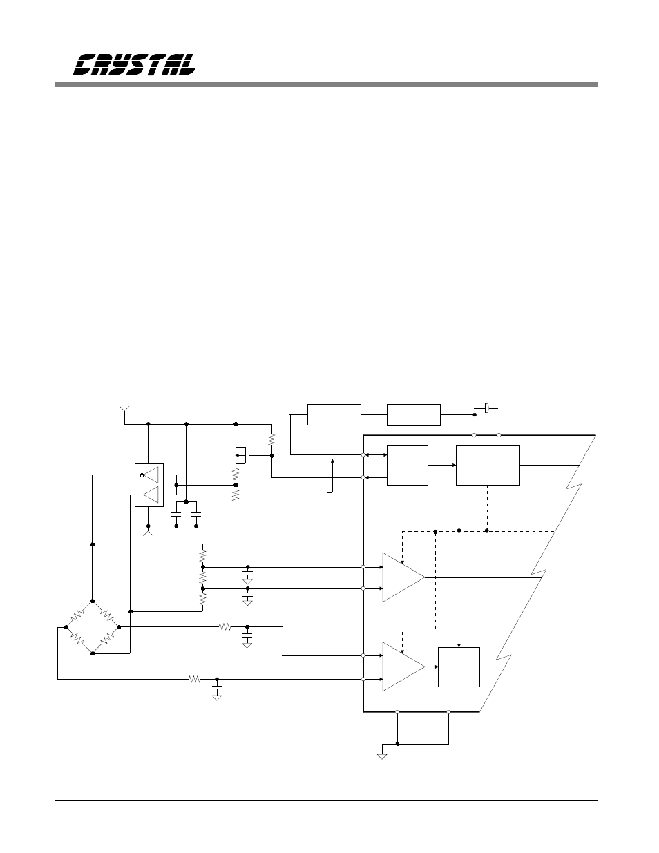
decade divider (74HC4017) can be followed by
a binary 2
14
divider (74HC4020) to yield a
25 Hz excitation frequency. The converter will
output conversion words at a 50 Hz rate, or two
output words for each one cycle of the bridge
excitation. The 25 Hz excitation reduces the
switching frequency of the bridge so the circuit
spends more time measuring and less time
settling. This will improve measurement
performance, but multiple output words (an even
number of them) must be averaged to ensure
equal samples for both polarities of the
excitation clock. Figure 15 illustrates this
circuit. Note that the details on connecting the
clock divider chips have not been shown to
simplify the schematic.
CS5516/CS5520 with AC-Excitation
Controlled by a Microcontroller
If the load cell cables are very long, the
capacitance may be so large that the circuit
cannot settle and yield an accurate result with
the 25 Hz circuit. Another option exist. Rather
than use the counters in Figure 15 to control the
BX1 signal and the drive polarity, one can use a
microcontroller output line. With the converter
set up in the external excitation mode, the
microcontroller can control the polarity of the
100k
10k
10k
4.096 MHz
BX2
XIN
XOUT
TP0610
+
10
0.1
2
4
+5
-
VREF-
VREF+
6
7
5
3
R1
R3
R2
7.5k
5k
7.5k
-5
+
301
4.7 nF
AIN+
AGND1
AGND2
AIN-
MICREL
MIC4428
Bridge
Sync
+
_
1X
+
_
25X
Gain
Block
1,2,4,8
Calibration
BX1
470pF
470pF
74HC4017
÷
10
74HC4020
25Hz
CS5520
16 or 20 bits
301
4.7 nF
÷
2
14
CS5516
See Text
for another
control option.
25 Conversions/sec averaging required
Figure 15. CS5516 with External 25 Hz AC Excitation.
Bridge Transducer Digitizer Circuits
20
AN31REV3