Bridge transducer digitizer circuits – Cirrus Logic AN31 User Manual
Page 5
negative offset into the amplifier and the zero
trim is used to finely adjust this offset. With zero
weight on the scale, the zero trim is adjusted to
yield -30,000 counts if the CS5507 16-bit A/D is
used or to -500,000 counts if a 20-bit CS5508 is
used. With full scale weight on the scale the gain
trim is adjusted for +30,000 counts in the
CS5507 or +500,000 counts in the CS5508
(Note that the CS5507 and CS5508 are pin
compatible). This leaves some counts for both
zero underflow and for overrange. The amplifier
components set the bandwidth to 45 Hz. With
the 45 Hz bandwidth, the circuit exhibits about
50,000 noise-free counts. With an external 162
kHz clock, the converter can operate at 100
conversions per second. If 20 conversion words
from the CS5508 are averaged, the circuit will
yield more than 200,000 noise-free counts. A
limitation of this circuit is that the bipolar
amplifiers can exhibit significant offset drift as
the temperature changes. There are several
circuits in this application note which will show
how to overcome offset drift.
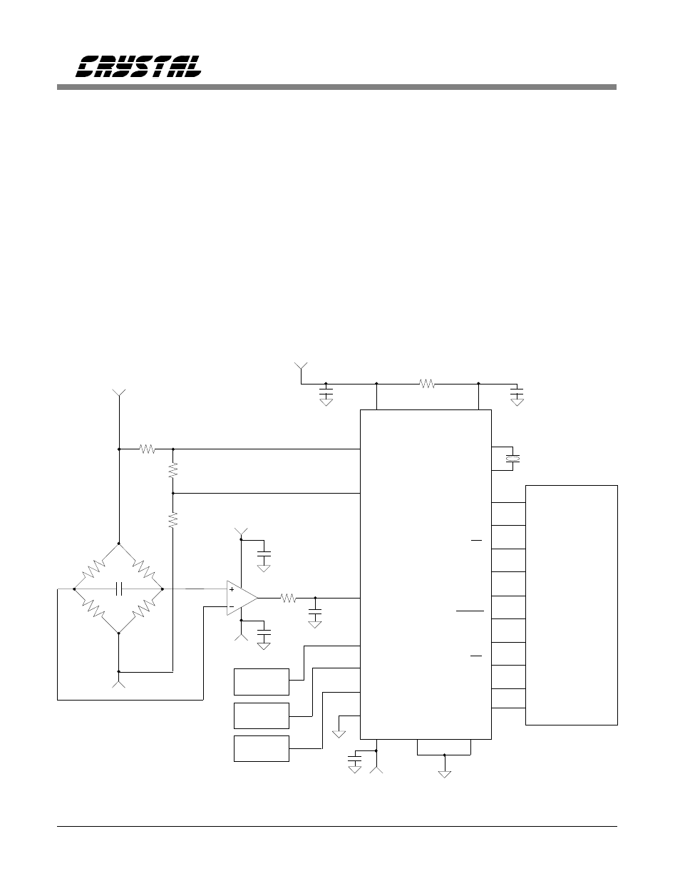
CS5505/6 Operating From
±
5 V Supplies
The CS5504/5/6/7/8 converters (not the CS5509)
can be operated with
±
5 V on the analog section
of the converter, and with either +5 V or +3.3 V
on the digital section.
0.1
+5
VA+
VREF+
VREF-
AIN1+
CS5505
CS5506
16 or
20 bits
AIN-
VREFOUT
VA-
DGND
SCLK
SDATA
CONV
CAL
XIN
XOUT
32.768kHz
350
350
350
350
5k
3
2
6
A0
A1
≈
2.5 V
17
4
3
2
1
24
23
22
8
21
5
6
14
CS
DRDY
BP/UP
19
16
18
9
15
7.5k
7.5k
2 mV/V
-5
4
7
2.4k
+5
x100
11
0.47
INA131
Bridge Amp
#2
#3
#4
AIN4+
13
AIN3+
12
AIN2+
10
0.1
+5
0.1
Microcontroller
System
2mV/V
Transducer
0.1
0.1
-
+
0.1
20
VD+
10
-5
-5
M/SLP
7
20 Conversions/sec
Figure 5. CS5505/6 Operating from
±
5V Supplies.
Bridge Transducer Digitizer Circuits
AN31REV3
5