Cirrus Logic AN362 User Manual
An362, Introduction, Test setup
Copyright
Cirrus Logic, Inc. 2012
(All Rights Reserved)
Cirrus Logic, Inc.
Application Note
CS5480/84/90 Measurement Accuracy
vs. IEC Standards
1. Introduction
Cirrus Logic’s CS5480, CS5484, and CS5490 energy measurement ICs benefit from on-chip, high-performance, 24-
bit ADC converters in conjunction with its digital calibration and compensation algorithms. This application note pres-
ents accuracy results from testing the CS5480. The CS5484 and CS5490 uses the same core technology as the
CS5480. Testing results of the CS5484 and CS5490 show nearly identical results.
The CS5480 has world-leading accuracy over an extensive, dynamic range. This application note cites measure-
ments of active energy, reactive energy, and I
RMS
load performance acquired from the CS5480 using three different
types of current sensor: Rogowski coil, current transformer (CT), and shunt. A comparison between the CS5480
measurements and the IEC 62053 standards is presented. This comparison shows that the CS5480 meets IEC
62053-22 class 0,2S standards for active energy and IEC 62053-23 class 2 standards for reactive energy. Compar-
ison with the ANSI C12.20 standard is not included in this application note because the ANSI standard is less strin-
gent than the IEC 62053 standard, so it is implied that the CS5480 meets it.
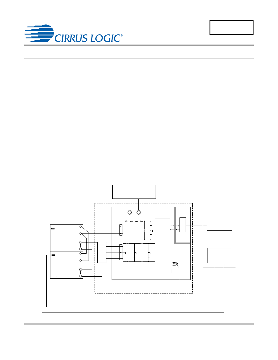
2. Test Setup
The following diagram illustrates the connections between the PPS400.3 power source, PRS400.3 power reference,
current sensor, CDB5480U board (+3.3V DC power supply), and a host PC.
Power Source
U
n
I
b
CS5480
VIN 1+
VIN 1-
N3
U3
CDB5480U
I3
PPS400.3
Power Reference
U3
N3
I3
PRS400.3
Energy Pulses
+3.3V DC Power Supply
+3.3V
GND
USB
M
C
U
DO1
TX
RX
PC
CDB5480U GUI
CAMCAL
®
for
WINDOWS
RS232
RS232
Current
Sensor
METER
SH2003
IIN1-
IIN1+
27n
27n
1K
100
1K
100
27n
27n
GND
IIN1-
IIN1+
J1
V+
V-
GND
27n
27n
LINE 1
GND
J4
422K 422K
422K
422K
1K
Figure 1. Test Setup Connection Diagram
AN362
MAR’12
AN362REV1
Document Outline
- 1. Introduction
- 2. Test Setup
- 3. Accuracy Test with Rogowski Coil, Un = 240 V and Ib(max) = 2 (80 A) at 50 Hz
- 4. Accuracy Test with Current Transformer CT, Un = 240 V and Ib(max) = 2.5 (100 A) at 50 Hz
- 5. Accuracy Test with Shunt, Un = 240 V and Ib(max) = 2.5 (100 A) at 50 Hz
- 6. Summary
- 7. Revision History