Table 2. cs5381 common master clock frequencies, 2 slave mode, Table 3. cs5381 slave mode clock ratios – Cirrus Logic CS5381 User Manual
Page 16: 3 power-up sequence, 4 analog connections, 3 power-up sequence 3.4 analog connections, Table 2, For com, Cs5381
16
DS563F2
CS5381
3.2.2
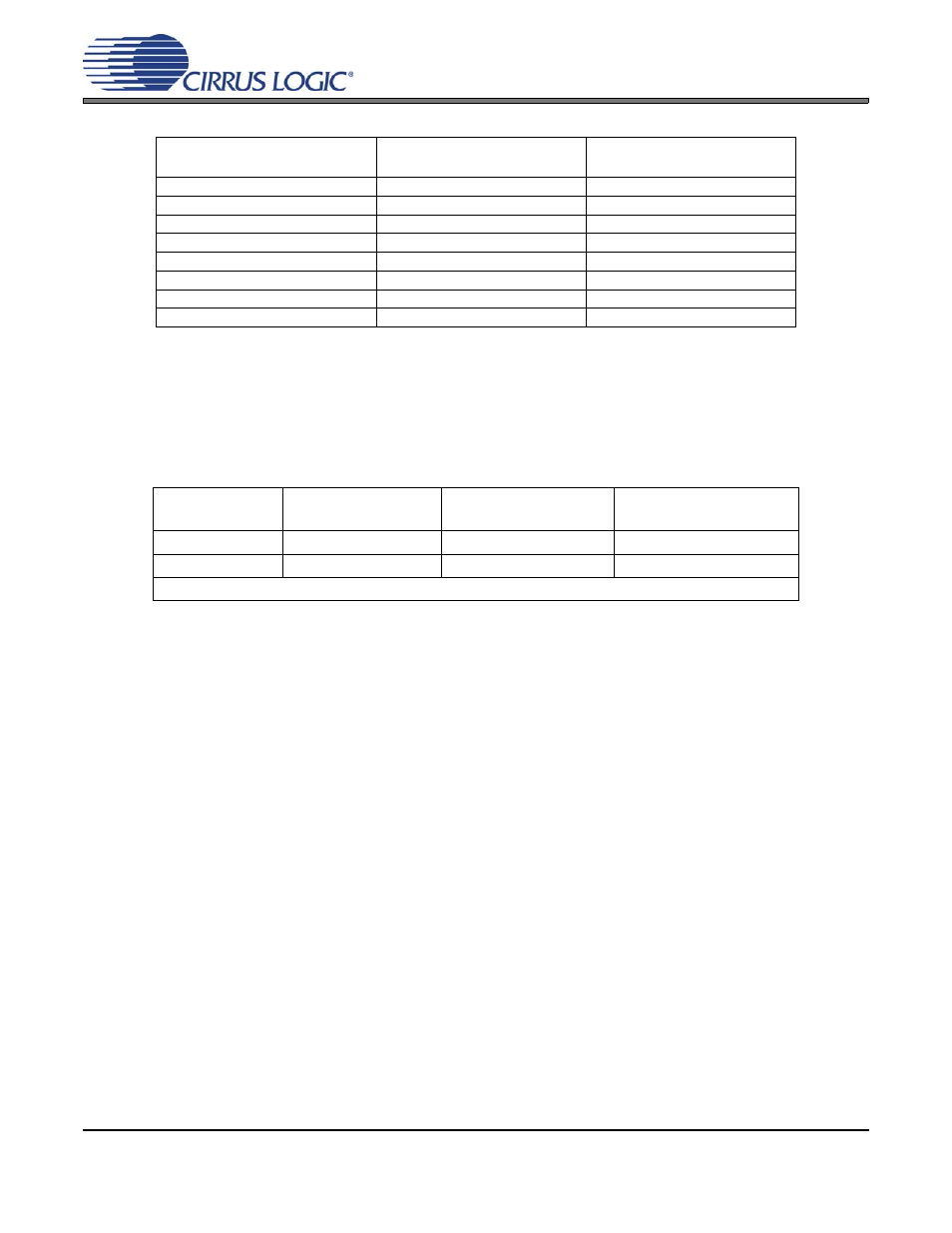
Slave Mode
LRCK and SCLK operate as inputs in Slave mode. It is recommended that the left/right clock be synchro-
nously derived from the master clock and must be equal to Fs. It is also recommended that the serial clock
be synchronously derived from the master clock and be equal to 64x Fs to maximize system performance.
Refer to
for required clock ratios.
Table 3. CS5381 Slave Mode Clock Ratios
3.3
Power-Up Sequence
Reliable power-up can be accomplished by keeping the device in reset until the power supplies, clocks and
configuration pins are stable. It is also recommended that reset be enabled if the analog or digital supplies
drop below the minimum specified operating voltages to prevent power glitch related issues.
The internal reference voltage must be stable for the device to produce valid data. Therefore, there is a de-
lay between the release of reset and the generation of valid output, due to the finite output impedance of
FILT+ and the presence of the external capacitance. This duration of this delay is less than 2500 LRCK cy-
cles.
3.4
Analog Connections
The analog modulator samples the input at 6.144 MHz. The digital filter will reject signals within the stop-
band of the filter. However, there is no rejection for input signals which are (n
×
6.144 MHz) the digital pass-
band frequency, where n=0,1,2,... Refer to
, which shows the suggested filter that will attenuate
any noise energy at 6.144 MHz in addition to providing the optimum source impedance for the modulators.
The use of capacitors which have a large voltage coefficient (such as general purpose ceramics) must be
avoided since these can degrade signal linearity. C0G capacitors are recommended for this application.
SAMPLE RATE (kHz)
MDIV = 0
MCLK (MHz)
MDIV = 1
MCLK (MHz)
32
8.192
16.384
44.1
11.2896
22.5792
48
12.288
24.576
64
8.192
16.384
88.2
11.2896
22.5792
96
12.288
24.576
176.4
11.2896
22.5792
192
12.288
24.576
Table 2. CS5381 Common Master Clock Frequencies
Single-Speed Mode
Fs = 2 kHz to 54 kHz
Double-Speed Mode
Fs = 50 kHz to 108 kHz
Quad-Speed Mode
Fs = 100 kHz to 216 kHz
MCLK/LRCK Ratio
256x, 512x
128x, 256x
64x*, 128x
SCLK/LRCK Ratio
64x, 128x
64x
64x
* Only available in Master mode.