Cs5368 – Cirrus Logic CS5368 User Manual
Page 8
8
DS624F5
CS5368
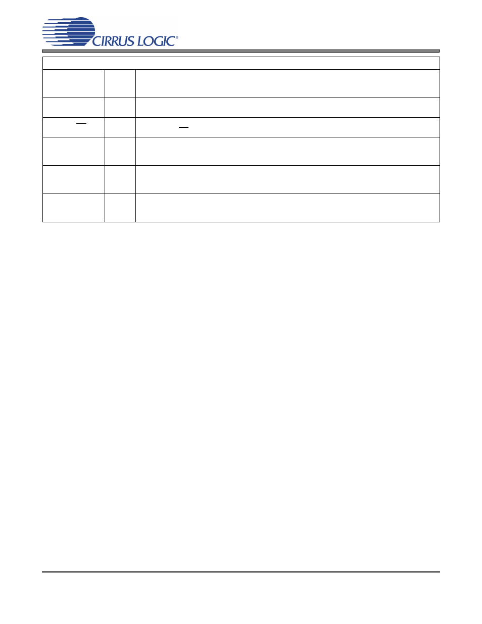
Control Port Mode
CLKMODE
34
CLKMODE (Input) - This pin is ignored in Control Port Mode and the same functionality is
obtained from the corresponding bit in the Global Control Register. Note: Should be connected
to GND when using the part in Control Port Mode.
AD1/CDIN
37
I²C Format, AD1 (Input) - Forms the device address input AD[1].
SPI Format, CDIN (Input) - Becomes the input data pin.
AD0/CS
38
I²C Format, AD0 (Input) - Forms the device address input AD[0].
SPI Format, CS (Input) - Acts as the active low chip select input.
SCL/CCLK
39
I²C Format, SCL (Input) – Serial clock for the serial control port. An external pull-up resistor is
required for I²C control port operation.
SPI Format, CCLK (Input) – Serial clock for the serial control port.
SDA/CDOUT
40
I²C Format SDA (Input/Output) - Acts as an input/output data pin. An external pull-up resistor is
required for I²C control port operation.
SPI Format CDOUT (Output) - Acts as an output only data pin.
MDIV
42
MCLK Divider (Input) - This pin is ignored in Control Port Mode and the same functionality is
obtained from the corresponding bit in the Global Control Register.
Note: Should be connected to GND when using the part in Control Port Mode.