Package dimensions, Thermal characteristics – Cirrus Logic CS5344 User Manual
Page 18
18
DS687F4
CS5343/4
Draft
2/1/11
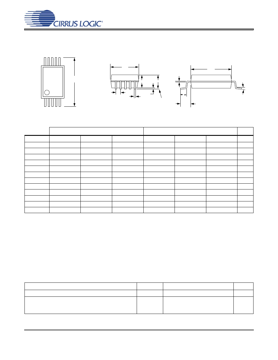
7. PACKAGE DIMENSIONS
Notes:
1.
Reference document: JEDEC MO-187
2.
D does not include mold flash or protrusions, which is 0.15 mm max. per side.
3.
E1 does not include inter-lead flash or protrusions, which is 0.15 mm max per side.
4.
Dimension b does not include a total allowable dambar protrusion of 0.08 mm max.
5.
Exceptions to JEDEC dimension.
THERMAL CHARACTERISTICS
INCHES
MILLIMETERS
NOTE
DIM
MIN
NOM
MAX
MIN
NOM
MAX
A
--
--
0.0433
--
--
1.10
A1
0
--
0.0059
0
--
0.15
A2
0.0295
--
0.0374
0.75
--
0.95
b
0.0059
--
0.0118
0.15
--
0.30
c
0.0031
--
0.0091
0.08
--
0.23
D
--
0.1181 BSC
--
--
3.00 BSC
--
E
--
0.1929 BSC
--
--
4.90 BSC
--
E1
--
0.1181 BSC
--
--
3.00 BSC
--
e
--
0.0197 BSC
--
--
0.50 BSC
--
L
0.0157
0.0236
0.0315
0.40
0.60
0.80
L1
--
0.0374 REF
--
--
0.95 REF
--
µ
0°
--
8°
0°
--
8°
Controlling Dimension is Millimeters
Parameter
Symbol
Min
Typ
Max
Unit
Allowable Junction Temperature
T
J
-
-
135
C
Junction to Ambient Thermal Impedance
(4-layer PCB)
(2-layer PCB)
JA-4
JA-2
-
-
100
170
-
-
C/W
C/W
10LD TSSOP (3 mm BODY) PACKAGE DRAWING
E
N
1 2 3
e
b
A1
A2
A
D
SEATING
PLANE
E1
1
L
SIDE VIEW
END VIEW
TOP VIEW
L1
c